## Diagram: Processor Architecture
### Overview
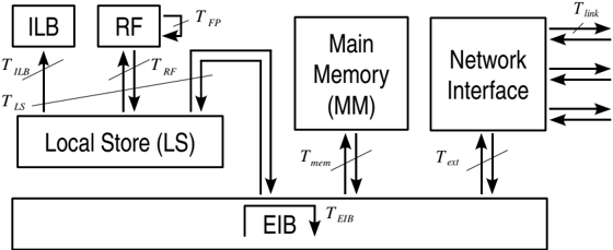
The image is a block diagram illustrating the architecture of a processor, showing the interconnections between various components such as the Instruction Lookaside Buffer (ILB), Register File (RF), Local Store (LS), Main Memory (MM), Network Interface, and the EIB (likely a bus or interconnect). The diagram also indicates the communication paths and associated latencies between these components.
### Components/Axes
* **ILB:** Instruction Lookaside Buffer
* **RF:** Register File
* **LS:** Local Store
* **MM:** Main Memory
* **Network Interface**
* **EIB:** (Likely a bus or interconnect)
* **T<sub>ILB</sub>:** Latency between ILB and LS
* **T<sub>RF</sub>:** Latency between RF and LS
* **T<sub>FP</sub>:** Latency for feedback within RF
* **T<sub>mem</sub>:** Latency between MM and EIB
* **T<sub>ext</sub>:** Latency between Network Interface and EIB
* **T<sub>link</sub>:** Latency associated with the Network Interface
* **T<sub>EIB</sub>:** Latency associated with the EIB
### Detailed Analysis
* **ILB (Instruction Lookaside Buffer):** Located at the top-left. Connected to the Local Store (LS) via a bidirectional arrow, labeled with T<sub>ILB</sub> and T<sub>LS</sub>.
* **RF (Register File):** Located to the right of the ILB. It has a self-loop arrow labeled T<sub>FP</sub>, indicating a feedback path. It is connected to the Local Store (LS) via a bidirectional arrow labeled T<sub>RF</sub>.
* **Local Store (LS):** Located below the ILB and RF. It connects to the ILB and RF as described above. It also has a downward arrow connecting it to the EIB.
* **Main Memory (MM):** Located to the right of the RF and above the EIB. It is connected to the EIB via a bidirectional arrow labeled T<sub>mem</sub>.
* **Network Interface:** Located to the right of the Main Memory. It has multiple arrows pointing outwards, labeled T<sub>link</sub>, indicating network connections. It is connected to the EIB via a bidirectional arrow labeled T<sub>ext</sub>.
* **EIB:** Located at the bottom, spanning the width of the diagram. It connects to the Local Store, Main Memory, and Network Interface. The connection to the Local Store is a downward arrow, while the connections to the Main Memory and Network Interface are bidirectional. The connection to the Local Store is not labeled, but the connection to the EIB is labeled T<sub>EIB</sub>.
### Key Observations
* The diagram highlights the data flow and communication latencies between different processor components.
* The Local Store (LS) acts as a central hub, connecting the ILB, RF, and EIB.
* The Network Interface facilitates external communication.
* The EIB appears to be a central interconnect or bus that allows communication between the Local Store, Main Memory, and Network Interface.
### Interpretation
The diagram represents a high-level view of a processor architecture, emphasizing the communication pathways and associated latencies between key components. The presence of the ILB and RF suggests a pipelined or out-of-order execution model. The Local Store likely serves as a fast, on-chip memory for frequently accessed data. The EIB acts as a system bus, enabling communication between the core processing units (ILB, RF, LS), the main memory, and the network interface. The latencies (T<sub>ILB</sub>, T<sub>RF</sub>, T<sub>mem</sub>, T<sub>ext</sub>, T<sub>link</sub>, T<sub>EIB</sub>, T<sub>LS</sub>, T<sub>FP</sub>) are critical parameters for performance analysis and optimization. The diagram suggests a system designed for both computation and communication, with a clear separation between local storage and external memory/network access.