\n
## Diagram: System Architecture with Data Flow
### Overview
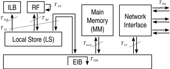
The image depicts a block diagram representing a system architecture with several components and data flow pathways. The components include an Instruction Lookaside Buffer (ILB), Register File (RF), Local Store (LS), Main Memory (MM), Network Interface, and an External Interface Bus (EIB). Arrows indicate the direction of data transfer between these components, each labeled with a corresponding time or latency parameter.
### Components/Axes
The diagram consists of the following components:
* **ILB:** Instruction Lookaside Buffer
* **RF:** Register File
* **LS:** Local Store
* **MM:** Main Memory
* **Network Interface:** Component for network communication
* **EIB:** External Interface Bus
The following time/latency parameters are labeled on the arrows:
* *T<sub>ILB</sub>*: Time associated with the ILB.
* *T<sub>LS</sub>*: Time associated with the Local Store.
* *T<sub>RF</sub>*: Time associated with the Register File.
* *T<sub>FP</sub>*: Time associated with the connection between RF and a small block.
* *T<sub>mem</sub>*: Time associated with Main Memory.
* *T<sub>ext</sub>*: Time associated with the Network Interface.
* *T<sub>link</sub>*: Time associated with the Network Interface's external links.
* *T<sub>EIB</sub>*: Time associated with the External Interface Bus.
### Detailed Analysis or Content Details
The diagram shows the following data flow:
* **ILB to LS:** Data flows from the ILB to the Local Store, labeled *T<sub>ILB</sub>*.
* **LS to MM:** Data flows from the Local Store to the Main Memory, labeled *T<sub>LS</sub>*.
* **RF to LS:** Data flows from the Register File to the Local Store, labeled *T<sub>RF</sub>*.
* **RF to a small block:** Data flows from the Register File to a small block, labeled *T<sub>FP</sub>*.
* **LS to MM:** Data flows from the Local Store to the Main Memory, labeled *T<sub>mem</sub>*.
* **MM to Network Interface:** Data flows from the Main Memory to the Network Interface, labeled *T<sub>ext</sub>*.
* **Network Interface to External:** Data flows from the Network Interface to external connections, labeled *T<sub>link</sub>*.
* **EIB to MM:** Data flows from the External Interface Bus to the Main Memory, labeled *T<sub>EIB</sub>*.
The components are arranged horizontally. The ILB and RF are positioned at the top-left, the LS is below them, the MM and Network Interface are in the center-right, and the EIB spans the bottom.
### Key Observations
The diagram illustrates a hierarchical memory system. The ILB and RF represent fast, small storage close to the processing unit, while the LS and MM represent larger, slower storage. The Network Interface provides connectivity to external networks. The EIB serves as an interface to external devices or systems. The diagram emphasizes the time/latency associated with each data transfer, suggesting performance optimization is a key consideration in the system design.
### Interpretation
This diagram likely represents a simplified model of a processor or a system-on-chip (SoC) architecture. The data flow and latency parameters suggest a focus on minimizing access times to frequently used data (ILB, RF) and efficiently managing data transfer between different levels of the memory hierarchy. The inclusion of a Network Interface indicates that the system is designed to communicate with external networks. The EIB provides a pathway for external interaction. The diagram highlights the importance of optimizing data flow paths to achieve high performance. The relative positioning of the components suggests a flow of data from fast, local storage to slower, more capacious storage and ultimately to external interfaces. The labeling of each connection with a time parameter (*T*) suggests that the design is concerned with minimizing latency and maximizing throughput.