## Diagram: Finite Control State
### Overview
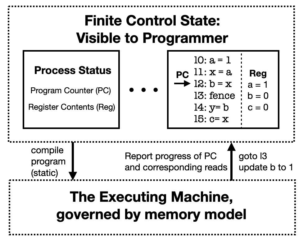
The image is a diagram illustrating the concept of a finite control state visible to a programmer, interacting with an executing machine. It shows the flow of information and control between the "Process Status" (including Program Counter and Register Contents) and the "Executing Machine."
### Components/Axes
* **Title:** Finite Control State: Visible to Programmer
* **Top Region:** Enclosed in a dotted rectangle.
* **Left Box:** Labeled "Process Status" containing "Program Counter (PC)" and "Register Contents (Reg)".
* **Middle:** Three dots indicating continuation or a sequence.
* **Right Box:** Contains program instructions and register values.
* Instructions are numbered 10 to 15.
* Register values for a, b, and c are shown.
* **Bottom Region:** Enclosed in a dotted rectangle.
* **Bottom Label:** "The Executing Machine, governed by memory model"
* **Arrows:**
* Downward arrow from "compile program (static)" to the bottom region.
* Upward arrow from the bottom region to the right box, labeled "Report progress of PC and corresponding reads" and "goto l3 update b to 1".
### Detailed Analysis or ### Content Details
* **Process Status Box:** Contains the elements "Program Counter (PC)" and "Register Contents (Reg)".
* **Program Instructions (Right Box):**
* 10: a = 1
* PC -> 11: x = a
* 12: b = x
* 13: fence
* 14: y = b
* 15: c = x
* **Register Values (Right Box):**
* a = 1
* b = 0
* c = 0
* **Arrows:**
* "compile program (static)" points downwards to "The Executing Machine, governed by memory model".
* "Report progress of PC and corresponding reads" and "goto l3 update b to 1" points upwards to the program instruction "13: fence". The arrow originates from "The Executing Machine, governed by memory model".
### Key Observations
* The diagram illustrates the interaction between the program's visible state (registers, program counter) and the underlying executing machine.
* The "fence" instruction at line 13 appears to trigger a report of progress and a jump back to itself, potentially indicating a loop or synchronization point.
* The register values are updated as the program executes.
### Interpretation
The diagram depicts a simplified model of how a programmer views the execution of a program. The "Finite Control State" represents the program's state that is directly observable and modifiable by the programmer. This includes the program counter (PC), which indicates the current instruction being executed, and the register contents, which store the program's data.
The "Executing Machine" represents the underlying hardware and software that actually executes the program. It is governed by a memory model, which defines how memory is accessed and managed.
The arrows show the flow of information and control between these two components. The "compile program (static)" arrow indicates that the program is compiled into a static representation that can be executed by the machine. The "Report progress of PC and corresponding reads" arrow indicates that the executing machine reports the progress of the program counter and the values of any memory locations that are read during execution. The "goto l3 update b to 1" arrow indicates that the executing machine can also modify the program's state, in this case by jumping to line 13 and updating the value of register b to 1.
The "fence" instruction is a synchronization primitive that ensures that all memory operations have completed before proceeding. In this case, the "fence" instruction triggers a report of progress and a jump back to itself, potentially indicating a loop or synchronization point.
Overall, the diagram illustrates the key concepts of program execution, including the separation of the program's visible state from the underlying executing machine, the flow of information and control between these two components, and the use of synchronization primitives to ensure correct execution.