## Diagram: Finite Control State vs. Executing Machine
### Overview
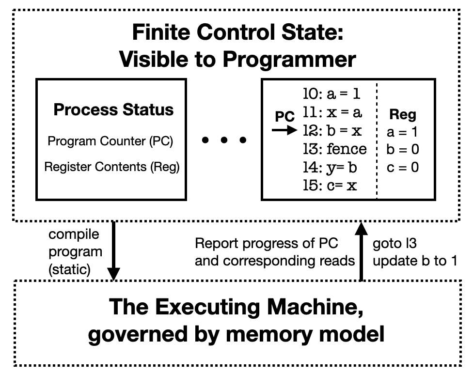
This technical diagram illustrates the conceptual separation and interaction between the high-level state of a program as seen by a programmer and the low-level execution of that program on a machine governed by a specific memory model. It depicts a feedback loop where static compilation moves code to the machine, and the machine reports execution progress and state changes back to the programmer-visible state.
### Components/Axes
The diagram is divided into two primary horizontal regions separated by a gap containing directional arrows.
* **Top Region (Dashed Boundary):** Labeled **"Finite Control State: Visible to Programmer"**. This represents the abstract state of the process, including the instruction sequence and register values.
* **Left Solid Box ("Process Status"):** Contains the labels "Program Counter (PC)" and "Register Contents (Reg)".
* **Center:** An ellipsis (**...**) indicating a transition or intermediate steps between the abstract definition and a specific state snapshot.
* **Right Solid Box (State Snapshot):** Divided by a vertical dashed line.
* **Left Side (Code):** A list of instructions with line numbers (10-15). A bold arrow labeled **"PC"** points to line 12.
* **Right Side ("Reg"):** A list of current register values.
* **Bottom Region (Dashed Boundary):** Labeled **"The Executing Machine, governed by memory model"**. This represents the actual hardware or virtual environment where execution occurs, constrained by rules like memory consistency models.
* **Interconnecting Arrows:**
* **Left Arrow (Downward):** Points from the Finite Control State to the Executing Machine. Label: **"compile program (static)"**.
* **Right Arrow (Upward):** Points from the Executing Machine back to the Finite Control State. It has two labels:
* Left of arrow: **"Report progress of PC and corresponding reads"**
* Right of arrow: **"goto 13 update b to 1"**
### Content Details
#### Code and Register State (Top-Right Box)
The diagram provides a specific snapshot of a program's execution state:
| Line Number | Instruction | Notes |
| :--- | :--- | :--- |
| 10 | `a = 1` | |
| 11 | `x = a` | |
| 12 | `b = x` | **Current Program Counter (PC) location** |
| 13 | `fence` | Memory barrier instruction |
| 14 | `y = b` | |
| 15 | `c = x` | |
**Register Contents (Reg):**
* `a = 1`
* `b = 0`
* `c = 0`
### Key Observations
* **Static vs. Dynamic:** The downward arrow indicates a one-time static compilation phase. The upward arrow indicates a continuous or iterative reporting of dynamic execution status.
* **PC Placement:** The Program Counter is currently at line 12 (`b = x`). However, the register `b` is still `0`, suggesting the instruction at line 12 has not yet completed its write-back to the visible state, or the machine is reporting an impending update.
* **Feedback Mechanism:** The upward arrow explicitly mentions "update b to 1", which corresponds to the logic of line 12 (since `x` would be `1` from line 11). It also mentions "goto 13", indicating the PC is advancing.
* **Memory Model Influence:** The bottom box emphasizes that the machine is "governed by memory model," which explains why the "fence" instruction (line 13) is present—it is a tool used by the programmer to control the machine's behavior regarding instruction reordering or memory visibility.
### Interpretation
This diagram demonstrates the **decoupling of program logic from execution reality**.
1. **Abstraction Layer:** The "Finite Control State" is the programmer's mental model—a sequential, predictable flow of instructions and register updates.
2. **Execution Layer:** The "Executing Machine" may perform optimizations (like out-of-order execution or speculative execution) allowed by its "memory model."
3. **Synchronization:** The upward arrow represents the "Commit" or "Retirement" phase of execution, where the machine's internal, potentially non-sequential actions are reconciled back into the sequential "Visible to Programmer" state.
4. **The Role of the Fence:** The inclusion of a `fence` instruction suggests this diagram is likely discussing **weak memory models**. In such models, the machine might try to execute line 14 or 15 before line 12 is fully visible to other processors; the `fence` at line 13 acts as a synchronization point to prevent certain types of reordering, ensuring the "Visible to Programmer" state remains consistent with the programmer's expectations.
5. **Peircean Investigation:** The "goto 13 update b to 1" text is an indexical sign of a state transition. It shows the exact moment the machine "reports" its internal progress to the abstract architectural state. The discrepancy between the PC pointing at line 12 and the instruction to "goto 13" suggests the diagram captures the transition *between* cycles or the latency between execution and architectural commitment.