\n
## Diagram: Finite Control State & Execution Machine
### Overview
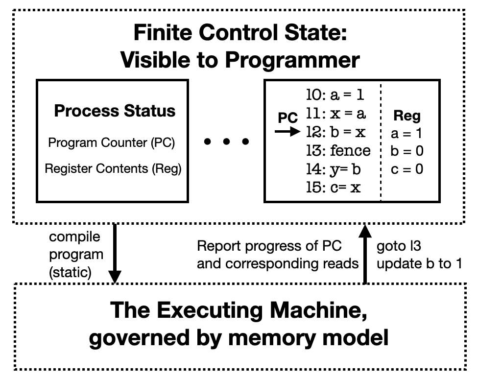
This diagram illustrates the relationship between the "Finite Control State" visible to a programmer and "The Executing Machine" governed by a memory model. It depicts how program instructions are executed, showing the flow of the Program Counter (PC) and the updates to register contents. The diagram uses a combination of boxes, arrows, and text to represent these concepts.
### Components/Axes
The diagram is divided into three main sections:
1. **Finite Control State: Visible to Programmer** (Top-left): This section represents the programmer's view of the system state. It contains a box labeled "Process Status" with two sub-components: "Program Counter (PC)" and "Register Contents (Reg)".
2. **Execution Flow & Instructions** (Center): This section shows the execution flow represented by a series of instructions (l0-l5) and the Program Counter (PC) pointing to the current instruction. A "Reg" box displays the current register values.
3. **The Executing Machine, governed by memory model** (Bottom): This section represents the underlying execution machine and its interaction with the control state.
There are also several arrows indicating the flow of control and data:
* "compile program (static)" - from the Finite Control State to the Executing Machine.
* "Report progress of PC and corresponding reads" - from the Executing Machine to the Finite Control State.
* "goto l3 update b to 1" - from the Executing Machine to the Execution Flow & Instructions.
### Detailed Analysis or Content Details
**Finite Control State:**
* **Process Status:** Contains the Program Counter (PC) and Register Contents (Reg).
* **Program Counter (PC):** An arrow points from the PC to instruction l0.
* **Register Contents (Reg):** Displays the following values:
* a = 1
* b = 0
* c = 0
**Execution Flow & Instructions:**
The following instructions are listed sequentially:
* l0: a = 1
* l1: x = a
* l2: b = x
* l3: fence
* l4: y = b
* l5: c = x
The Program Counter (PC) is shown pointing to instruction l0.
**The Executing Machine:**
* The section is enclosed in a dashed box.
* It is labeled "The Executing Machine, governed by memory model".
* Arrows indicate interactions with the Finite Control State and the Execution Flow.
### Key Observations
* The diagram illustrates a simplified model of program execution.
* The "fence" instruction (l3) suggests a memory barrier or synchronization point.
* The register values (a, b, c) are updated as the program executes.
* The "goto l3 update b to 1" arrow indicates that after executing l2, the program jumps to instruction l3 and updates the value of register 'b' to 1.
### Interpretation
The diagram demonstrates a basic execution model where the programmer interacts with a finite control state (PC and registers), while the underlying execution is handled by the executing machine governed by a memory model. The instructions (l0-l5) represent a sequence of operations that modify the register values. The "fence" instruction is crucial for maintaining memory consistency in concurrent systems. The diagram highlights the separation between the programmer's view of the program state and the actual execution process. The flow of control is represented by the Program Counter, which sequentially executes instructions. The arrows connecting the different sections illustrate the interaction between the control state and the execution machine. The update of 'b' to 1 after l2 and the jump to l3 suggests a conditional execution or a specific program logic.