## Diagram: Program Execution Model
### Overview
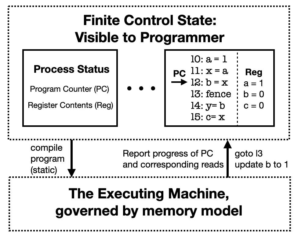
The image is a technical diagram illustrating a two-layer model of program execution. It separates the programmer-visible state from the underlying executing machine, connected by compilation and runtime interaction arrows. The diagram uses dashed boxes to denote major system boundaries and solid boxes for internal components.
### Components/Axes
The diagram is divided into two primary regions, top and bottom, enclosed by dashed rectangles.
**Top Region: "Finite Control State: Visible to Programmer"**
This region contains two solid rectangular boxes connected by an ellipsis (`...`), indicating a separation or interface between them.
1. **Left Solid Box: "Process Status"**
* **Title:** `Process Status`
* **Content:**
* `Program Counter (PC)`
* `Register Contents (Reg)`
2. **Right Solid Box: Code and Register State**
* **Left Column (Code):** A sequence of numbered instructions.
* `l0: a = 1`
* `l1: x = a`
* `l2: b = x` (An arrow labeled `PC` points directly to this line.)
* `l3: fence`
* `l4: y = b`
* `l5: c = x`
* **Right Column (Register State):** A column labeled `Reg` showing current register values.
* `a = 1`
* `b = 0`
* `c = 0`
**Bottom Region: "The Executing Machine, governed by memory model"**
This is a single dashed box containing only the title text.
**Interaction Arrows (Between Top and Bottom Regions):**
1. **Downward Arrow (Left):** Points from the top region to the bottom region.
* **Label:** `compile program (static)`
2. **Upward Arrow (Right):** Points from the bottom region to the top region.
* **Label (Upper Part):** `Report progress of PC and corresponding reads`
* **Label (Lower Part):** `goto l3 update b to 1`
### Detailed Analysis
* **Spatial Grounding:** The `PC` arrow in the right solid box is positioned to the left of the code list, pointing horizontally at line `l2`. The `Reg` column is vertically aligned to the right of the code list, separated by a dashed vertical line.
* **State Snapshot:** The diagram captures a specific moment in execution. The Program Counter (PC) is at line `l2` (`b = x`). The register state shows `a=1`, `b=0`, `c=0`. This implies that the instruction at `l1` (`x = a`) has executed (setting `x` to 1), but the instruction at `l2` (`b = x`) has not yet executed (as `b` is still 0).
* **Flow Indication:** The upward arrow's lower label (`goto l3 update b to 1`) suggests a potential or required runtime action: jumping to line `l3` and modifying the register `b` to 1. This appears to be an instruction or feedback from the executing machine to the visible control state.
### Key Observations
1. **Abstraction Boundary:** The diagram explicitly models a separation between the "Finite Control State" (the abstract machine state a programmer reasons about) and "The Executing Machine" (the physical or lower-level implementation governed by a memory model).
2. **Static vs. Dynamic:** Compilation (`compile program (static)`) is depicted as a one-way, static transformation from the programmer's model to the executing machine. Runtime interaction is shown as a dynamic, upward feedback loop.
3. **Instruction Fencing:** The presence of a `fence` instruction at line `l3` is notable. In concurrent programming, a fence (or barrier) is used to enforce ordering constraints on memory operations. Its placement here, and the suggested `goto l3`, may relate to enforcing memory model guarantees.
4. **Inconsistent State:** The register `b` is shown as `0` in the `Reg` column, but the upward arrow suggests an action to "update b to 1". This highlights a potential discrepancy or a pending operation that the executing machine must report or perform.
### Interpretation
This diagram illustrates a foundational concept in computer architecture and programming language semantics: the distinction between the **architectural state** (or ISA-level state) visible to a programmer/compiler and the **microarchitectural implementation** that actually executes instructions.
* **What it demonstrates:** It shows how a program (the code list) and its associated architectural state (PC, registers) are compiled into a form that the underlying machine executes. The machine then provides feedback to the visible state (PC progress, read events) and can influence it (e.g., via a `goto`).
* **Relationships:** The top box is the *specification* or *model* the programmer uses. The bottom box is the *implementation*. The arrows represent the compilation process and the runtime interface between them. The `fence` instruction and the `goto`/`update` command suggest this model is particularly concerned with memory consistency and control flow in a concurrent or relaxed-memory setting.
* **Anomalies/Notable Points:** The core tension in the diagram is between the static, sequential code view and the dynamic, potentially non-sequential actions of the executing machine (like jumping to a fence and updating a register). This captures the complexity of mapping simple sequential code to real hardware that may reorder operations or require explicit synchronization. The diagram serves as a conceptual map for understanding how high-level program order relates to low-level execution events under a specific memory model.