## Diagram: Finite Control State: Visible to Programmer
### Overview
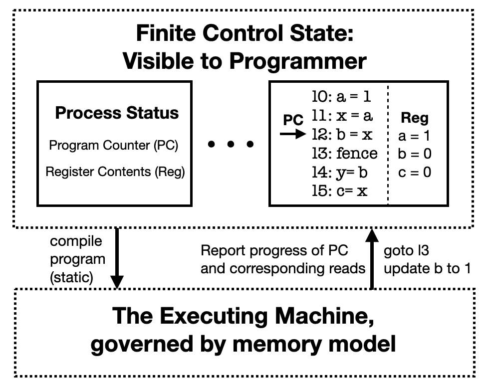
The diagram illustrates the finite control state of a program as visible to a programmer, focusing on the relationship between the **Process Status** (Program Counter and Register Contents) and the **Executing Machine** governed by a memory model. It includes a flowchart-like structure showing instruction execution, register updates, and control flow.
### Components/Axes
1. **Top Section**:
- **Process Status**: Contains two sub-components:
- **Program Counter (PC)**: Lists program lines (10–15) with code snippets (e.g., `a = 1`, `x = a`).
- **Register Contents (Reg)**: Shows variable states (`a = 1`, `b = 0`, `c = 0`).
- Arrows indicate flow between PC and Register Contents.
2. **Middle Section**:
- **Code Execution Flow**:
- Line 10: `a = 1`
- Line 11: `x = a`
- Line 12: `b = x` (with an arrow pointing to "goto l3")
- Line 13: `fence` (barrier instruction)
- Line 14: `y = b`
- Line 15: `c = x`
- Arrows show sequential execution and conditional jumps (e.g., `goto l3`).
3. **Bottom Section**:
- **Executing Machine**: Governed by a memory model, with bidirectional arrows connecting to the Process Status.
- Labels:
- "compile program (static)" (downward arrow from Process Status).
- "Report progress of PC and corresponding reads" (upward arrow to PC).
- "goto l3 update b to 1" (rightward arrow from PC).
### Detailed Analysis
- **Program Counter (PC)**:
- Lines 10–15 represent sequential instructions.
- Line 12 (`b = x`) triggers a jump to line 13 (`fence`), indicating a memory barrier.
- The `goto l3` instruction suggests a loop or conditional branch.
- **Register Contents (Reg)**:
- Variables `a`, `b`, and `c` are initialized and updated:
- `a = 1` (Line 10).
- `b = 0` (Line 13, updated to `1` via `goto l3`).
- `c = 0` (Line 15).
- **Control Flow**:
- The `fence` instruction (Line 13) acts as a synchronization point, ensuring memory operations before and after are ordered.
- The `goto l3` instruction creates a loop, updating `b` to `1` after the barrier.
### Key Observations
1. **Register Updates**:
- `b` is modified twice: initially set to `0` (Line 13) and later updated to `1` via the loop (Line 12 → `goto l3`).
2. **Memory Barrier**:
- The `fence` instruction (Line 13) enforces ordering between memory operations, critical for concurrent execution.
3. **Static Compilation**:
- The program is compiled statically, as indicated by the label "compile program (static)."
### Interpretation
This diagram demonstrates how a program’s control state is managed during execution. The **Program Counter** tracks instruction progress, while **Register Contents** reflect variable states. The **Executing Machine** enforces memory model rules, ensuring correct behavior through synchronization (e.g., `fence`) and control flow (e.g., `goto`). The loop (`goto l3`) and register updates highlight dynamic state changes, emphasizing the interplay between static compilation and runtime execution.
The diagram underscores the importance of memory barriers in preventing race conditions and ensuring deterministic outcomes in multi-threaded or concurrent environments. The static compilation ensures the program’s structure is fixed, while the executing machine dynamically manages state transitions.