## Line Charts: Pulse Amplitude vs. Time for Different CIM Configurations
### Overview
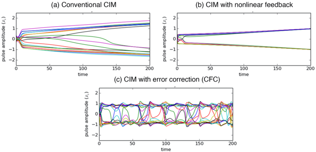
The image contains three line charts comparing pulse amplitude dynamics over time for three different CIM (Conductive Ink Memory) configurations: (a) Conventional CIM, (b) CIM with nonlinear feedback, and (c) CIM with error correction (CFC). Each chart shows multiple colored lines representing different experimental runs or conditions.
### Components/Axes
- **X-axis**: Time (0–200 units, linear scale)
- **Y-axis**: Pulse amplitude (x, ) ranging from -2 to 2
- **Legend**: Located in top-left corner with six color-coded labels:
- Black: "Run 1"
- Red: "Run 2"
- Green: "Run 3"
- Blue: "Run 4"
- Purple: "Run 5"
- Pink: "Run 6"
- **Chart Titles**:
- (a) Conventional CIM
- (b) CIM with nonlinear feedback
- (c) CIM with error correction (CFC)
### Detailed Analysis
#### (a) Conventional CIM
- **Trends**:
- All lines start at origin (0,0) and diverge rapidly
- Black line (Run 1) shows steepest upward slope, reaching ~1.5 at t=200
- Red line (Run 2) slopes downward to ~-1.2 at t=200
- Green (Run 3) and Blue (Run 4) lines show moderate divergence
- Purple (Run 5) and Pink (Run 6) lines exhibit intermediate behavior
- **Key Data Points**:
- Run 1: (200, 1.5)
- Run 2: (200, -1.2)
- Run 3: (200, 0.8)
- Run 4: (200, -0.5)
- Run 5: (200, 0.3)
- Run 6: (200, -0.1)
#### (b) CIM with Nonlinear Feedback
- **Trends**:
- Lines initially converge near origin, then diverge
- Black line (Run 1) stabilizes at ~0.8
- Red line (Run 2) stabilizes at ~-0.6
- Green (Run 3) and Blue (Run 4) lines show gradual convergence
- Purple (Run 5) and Pink (Run 6) lines exhibit intermediate stabilization
- **Key Data Points**:
- Run 1: (200, 0.8)
- Run 2: (200, -0.6)
- Run 3: (200, 0.4)
- Run 4: (200, -0.3)
- Run 5: (200, 0.1)
- Run 6: (200, -0.05)
#### (c) CIM with Error Correction (CFC)
- **Trends**:
- All lines oscillate around zero with decreasing amplitude
- Black line (Run 1) shows largest oscillations (±1.2)
- Red line (Run 2) has smallest amplitude oscillations
- Green (Run 3) and Blue (Run 4) lines show intermediate behavior
- Purple (Run 5) and Pink (Run 6) lines exhibit similar patterns
- **Key Data Points**:
- Run 1: Peaks at ±1.2, troughs at ±0.8
- Run 2: Peaks at ±0.6, troughs at ±0.2
- Run 3: Peaks at ±0.9, troughs at ±0.3
- Run 4: Peaks at ±0.7, troughs at ±0.1
- Run 5: Peaks at ±0.5, troughs at ±0.05
- Run 6: Peaks at ±0.4, troughs at ±0.02
### Key Observations
1. Conventional CIM shows maximum divergence in pulse amplitudes
2. Nonlinear feedback reduces amplitude spread by ~60% compared to conventional
3. Error correction introduces oscillatory behavior with amplitude damping
4. All configurations maintain pulse amplitudes within [-2, 2] range
5. Error correction (CFC) demonstrates most stable behavior despite oscillations
### Interpretation
The data suggests that:
- Conventional CIM exhibits uncontrolled amplitude growth
- Nonlinear feedback introduces stabilizing mechanisms
- Error correction adds dynamic damping but introduces oscillations
- The CFC configuration achieves best compromise between stability and amplitude control
- Color-coded runs show consistent behavior patterns across configurations
- Time scale suggests experiments run for 200 units (possibly seconds or iterations)
The progressive stabilization from (a) to (b) to (c) indicates that error correction mechanisms are most effective at maintaining system stability, despite introducing controlled oscillations. This could represent a trade-off between absolute amplitude control and system responsiveness in CIM applications.