## Circuit and State Machine Diagram: Control System Architecture
### Overview
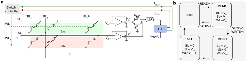
The image depicts a technical system architecture combining a circuit diagram (a) and a state machine diagram (b). The circuit diagram illustrates signal flow through a neural interface system, while the state machine defines operational logic for read/write operations.
### Components/Axes
**Circuit Diagram (a):**
- **Vertical Elements:**
- **Switch Controller**: Top-left box with green (→) and red (←) arrows
- **BL (Blue Lines)**: Labeled BL₁ to BLₙ, connected to green/red lines
- **SL (Blue Lines)**: Labeled SL₁ to SL₂, connected to excitation/inhibition regions
- **WL (Blue Lines)**: Labeled WL₁ to WL₂, connected to inhibition region
- **Horizontal Elements:**
- **Excitation Region**: Green-shaded area between BL₁ and BLₙ
- **Inhibition Region**: Red-shaded area below excitation region
- **I&F Circuit**: Contains operational amplifiers (V_rf, V_i) and feedback loop
- **LB (Load Block)**: Blue box connected to I&F circuit
- **Target_1**: Final output terminal
**State Machine Diagram (b):**
- **States**: IDLE, READ, SET, RESET
- **Transitions**:
- **READ → IDLE**: When STOP=1
- **IDLE → READ**: When READ=1
- **IDLE → SET**: When WRITE=1
- **SET → RESET**: When STOP#1=1
- **Variables**:
- BL = V_rd (READ), BL = 0 (SET), BL = V_rst (RESET)
- SL = V_rf (READ), SL = V_set (SET), SL = 0 (RESET)
- WL = V_dd (READ/IDLE), WL = V_c·I_cc (SET), WL = V_dd (RESET)
### Detailed Analysis
**Circuit Diagram:**
1. **Signal Flow**:
- Green lines (I_cc_et) originate from switch controller, pass through excitation region, and connect to I&F circuit
- Red lines (I_cc_it) originate from switch controller, pass through inhibition region, and connect to I&F circuit
- Blue lines (SL/WL) connect directly to excitation/inhibition regions
2. **Key Components**:
- **I&F Circuit**: Integrates excitatory (V_rf) and inhibitory (V_i) signals
- **LB Block**: Final processing unit before Target_1
- **Voltage References**: V_rd (read), V_rf (read), V_dd (default), V_rst (reset), V_set (set)
**State Machine Diagram:**
1. **Operational Logic**:
- **READ State**: Activates when READ=1, sets BL=V_rd, SL=V_rf, WL=V_dd
- **SET State**: Activates when WRITE=1, sets BL=0, SL=V_set, WL=V_c·I_cc
- **RESET State**: Activates when STOP#1=1, sets BL=V_rst, SL=0, WL=V_dd
- **IDLE State**: Default state with BL=V_rd, SL=V_rf, WL=V_dd
### Key Observations
1. **Signal Pathway**:
- Excitation (green) and inhibition (red) signals are spatially separated but converge at I&F circuit
- WL signals bypass excitation/inhibition regions, connecting directly to inhibition region
2. **State Machine Behavior**:
- READ/SET/RESET states modify BL/SL/WL voltages based on operational requirements
- STOP conditions (STOP=1/STOP#1) trigger state transitions
3. **Voltage Relationships**:
- V_c·I_cc (SET state) suggests current-controlled voltage generation
- V_rst (reset) and V_set (set) define distinct operational thresholds
### Interpretation
The system implements a closed-loop neural interface with:
1. **Dual-Path Signal Processing**:
- Excitation (green) and inhibition (red) pathways provide parallel signal modulation
- WL signals (blue) enable direct inhibition without passing through excitation region
2. **State-Dependent Control**:
- READ state prepares system for data acquisition (BL=V_rd, SL=V_rf)
- SET state configures synaptic weights (WL=V_c·I_cc)
- RESET state restores default parameters (BL=V_rst, SL=0)
3. **Safety Mechanisms**:
- STOP conditions prevent uncontrolled state transitions
- Default voltages (V_dd) maintain system stability during IDLE
The architecture demonstrates a sophisticated balance between analog signal processing (circuit diagram) and digital control logic (state machine), enabling precise modulation of neural interfaces through coordinated voltage control and operational state management.