## Diagram: Aircraft Collision Avoidance Scenarios
### Overview
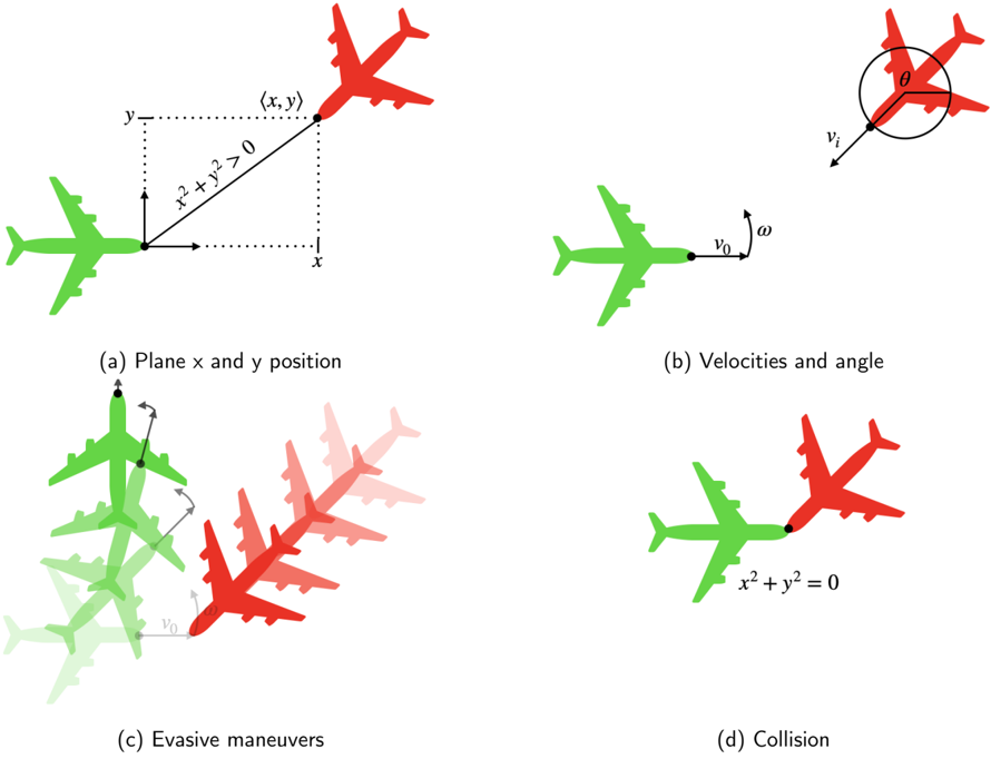
The image is a technical diagram illustrating four scenarios related to aircraft positioning, velocities, and collision dynamics. It uses color-coded airplanes (green for one aircraft, red for another) and mathematical annotations to model spatial relationships and motion.
### Components/Axes
1. **Section (a): Plane x and y position**
- **Axes**: Labeled `x` (horizontal) and `y` (vertical).
- **Planes**:
- Green airplane at the origin `(0,0)`.
- Red airplane at coordinates `(x,y)`, with the condition `x² + y² > 0` (indicating it is not at the origin).
- **Annotations**: Dotted lines form a right triangle to emphasize the distance between the planes.
2. **Section (b): Velocities and angle**
- **Velocities**:
- Green airplane: Velocity `v₀` (magnitude and direction unspecified).
- Red airplane: Velocity `v_i` at an angle `θ` relative to the green airplane’s velocity.
- **Angle**: `θ` is marked between the velocity vectors of the two planes.
3. **Section (c): Evasive maneuvers**
- **Planes**:
- Green airplane (origin) and red airplane (approaching).
- Multiple translucent red airplanes show a trajectory path.
- **Arrows**: Indicate motion direction for both planes.
- **Implication**: Demonstrates a sequence of evasive actions to avoid collision.
4. **Section (d): Collision**
- **Planes**: Overlapping at the origin `(0,0)`, with the equation `x² + y² = 0` explicitly labeled.
- **Interpretation**: Represents the collision point when no evasive action is taken.
### Detailed Analysis
- **Section (a)**: Establishes a 2D coordinate system to define the spatial relationship between the two aircraft. The red plane’s position `(x,y)` is constrained to non-origin points (`x² + y² > 0`).
- **Section (b)**: Introduces relative motion via velocities `v₀` and `v_i`, with `θ` quantifying the angular separation between their paths. This sets up the geometric conditions for potential collision.
- **Section (c)**: Visualizes dynamic evasive maneuvers, with the red plane altering its trajectory (via angular adjustments) to avoid intersecting paths with the green plane.
- **Section (d)**: Concludes with the collision scenario, mathematically enforced by `x² + y² = 0`, which collapses the distance to zero.
### Key Observations
1. **Mathematical Constraints**:
- The condition `x² + y² > 0` in (a) ensures the red plane starts at a non-zero distance from the green plane.
- The equation `x² + y² = 0` in (d) is a geometric representation of collision (only satisfied at the origin).
2. **Velocity-Angle Relationship**: The angle `θ` in (b) directly influences whether the planes’ paths intersect, determining the need for evasive action.
3. **Evasive Maneuver Dynamics**: The sequence in (c) implies that angular adjustments (`ω`) and velocity changes are critical to avoiding collision.
### Interpretation
This diagram models collision avoidance in aviation using basic kinematics and geometry.
- **Collision Avoidance Logic**: The red plane’s evasive maneuvers (section c) rely on modifying its velocity vector (`v_i`) and angle (`θ`) relative to the green plane’s trajectory (`v₀`).
- **Critical Thresholds**: The transition from `x² + y² > 0` (non-collision) to `x² + y² = 0` (collision) highlights the importance of timely course corrections.
- **Practical Implications**: The diagram underscores how angular separation (`θ`) and relative velocities (`v₀`, `v_i`) are key variables in air traffic control systems for predicting and preventing mid-air collisions.
No numerical values or data tables are present; the focus is on geometric and kinematic relationships.