## System Diagram: Neuromorphic Hardware Architecture
### Overview
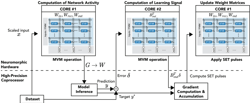
The image presents a system diagram illustrating a neuromorphic hardware architecture for network activity computation, learning signal computation, and weight matrix updates. It highlights the flow of data and operations between different cores and processing units, including a high-precision coprocessor.
### Components/Axes
* **Title:** The overall diagram lacks a central title, but the individual sections are titled.
* **Sections:** The diagram is divided into three main sections, each representing a core:
* Computation of Network Activity (CORE #1)
* Computation of Learning Signal (CORE #2)
* Update Weight Matrices (CORE #1)
* **Hardware Components:**
* Nueromorphic Hardware
* High-Precision Coprocessor
* **Data Flow:** Arrows indicate the direction of data flow between components.
* **Input/Output:**
* Scaled input *x*
* Target *y*^*
* Prediction *y*
* Error *δ*
* **Processing Blocks:**
* Model Inference
* Gradient Computation & Accumulation
* **Core Components:** Each core contains a matrix of "8T4R" elements, along with "ADC" (Analog-to-Digital Converter) blocks.
* **Inputs/PWM:** Each core receives inputs via "Inputs/PWM" (Pulse Width Modulation).
### Detailed Analysis
* **Computation of Network Activity (CORE #1):**
* Input: Scaled input *x* enters the system.
* Core Operation: Matrix-Vector Multiplication (MVM operation) is performed using weights *W*<sub>in</sub>, *W*<sub>rec</sub>, and *W*<sub>out</sub>.
* Output: The result *G* is passed to the Model Inference block.
* **Computation of Learning Signal (CORE #2):**
* Core Operation: MVM operation is performed using *B*<sub>out</sub><sup>T</sup>.
* Output: *B*<sub>out</sub><sup>T</sup> *δ* is passed to the Gradient Computation & Accumulation block.
* **Update Weight Matrices (CORE #1):**
* Core Operation: Applies SET pulses to update weight matrices *W*<sub>in</sub>, *W*<sub>rec</sub>, and *W*<sub>out</sub>.
* Input: Receives computed SET pulses from the Gradient Computation & Accumulation block.
* **Model Inference:**
* Input: Receives *G* from CORE #1.
* Operation: Performs model inference to generate a prediction *y*.
* **Gradient Computation & Accumulation:**
* Inputs: Receives *B*<sub>out</sub><sup>T</sup> *δ* from CORE #2 and the error signal from the comparator.
* Operation: Computes SET pulses for weight updates.
* **Dataset:** Provides the target value *y*^* for comparison.
* **Comparator:** Calculates the error *δ* between the prediction *y* and the target *y*^*.
* **8T4R Elements:** Each core contains a grid of 8T4R memory elements. The grid appears to be 3x3, but the middle row has an elipsis indicating that there are more rows.
* **ADC Blocks:** Analog-to-Digital Converters are present at the output of each row of 8T4R elements.
### Key Observations
* The architecture uses multiple cores to parallelize computations.
* MVM operations are central to both network activity and learning signal computations.
* The high-precision coprocessor handles model inference and gradient computation.
* The system uses a feedback loop to update weight matrices based on the error between prediction and target values.
* The dashed line separates the Neuromorphic Hardware from the High-Precision Coprocessor.
### Interpretation
The diagram illustrates a neuromorphic computing system designed for efficient machine learning tasks. The use of multiple cores allows for parallel processing of network activity and learning signals. The system employs a gradient-based learning approach, where the error between the model's prediction and the target value is used to update the weight matrices. The separation of neuromorphic hardware and a high-precision coprocessor suggests a hybrid approach, leveraging the strengths of both architectures. The 8T4R memory elements likely represent memristor-based synapses, enabling energy-efficient and compact storage of weights. The ADCs convert the analog outputs of the memristor arrays into digital signals for further processing.