## Diagram: Layered System Architecture
### Overview
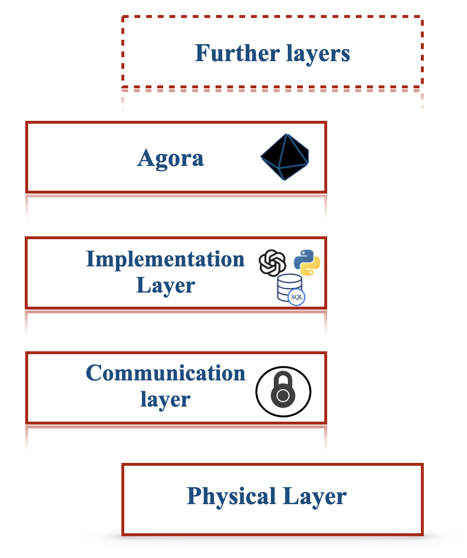
This diagram illustrates a layered system architecture, depicting distinct levels of functionality stacked vertically. The layers are presented from top to bottom, suggesting a hierarchical or dependency relationship. Each layer is represented by a rectangular box with a red border and contains a text label and, in some cases, associated icons. A dashed red border box at the top indicates "Further layers," implying this is an incomplete representation or a conceptual grouping.
### Components/Axes
The diagram does not have traditional axes or scales. The components are:
* **"Further layers"**: Enclosed in a dashed red border box, positioned at the top. This suggests additional, unspecified layers above the visible ones.
* **"Agora"**: A rectangular box below "Further layers." It contains the text "Agora" and a black geometric icon resembling a faceted polyhedron.
* **"Implementation Layer"**: A rectangular box below "Agora." It contains the text "Implementation Layer" and three icons:
* A stylized icon that appears to represent a network or interconnected nodes (possibly a logo for a specific technology).
* A Python logo (a blue and yellow snake).
* A stack of three discs with "SQL" written on the bottom disc, representing a database.
* **"Communication layer"**: A rectangular box below "Implementation Layer." It contains the text "Communication layer" and a black icon of a padlock.
* **"Physical Layer"**: A rectangular box at the bottom. It contains the text "Physical Layer."
The layers are arranged in a vertical stack, with "Further layers" at the highest conceptual level, followed by "Agora," "Implementation Layer," "Communication layer," and "Physical Layer" at the lowest visible level. The visual presentation suggests a top-down flow or dependency.
### Detailed Analysis or Content Details
The diagram presents a conceptual model of a system architecture. The layers are:
1. **Further layers**: This is a placeholder for additional, higher-level abstractions or functionalities not detailed in this diagram.
2. **Agora**: This layer is associated with a geometric icon. The term "Agora" historically refers to a public open space used for assemblies and markets in ancient Greece, suggesting a central hub or marketplace for interactions or data.
3. **Implementation Layer**: This layer is rich with icons indicating its function. The presence of a network/node icon, the Python logo (a popular programming language for development and data science), and an SQL database icon strongly suggest that this layer is responsible for the core logic, data management, and potentially the development environment of the system.
4. **Communication layer**: Represented by a padlock icon, this layer is clearly responsible for secure communication protocols and data exchange between different parts of the system or with external entities.
5. **Physical Layer**: This is the foundational layer, likely representing the underlying hardware, network infrastructure, and physical resources upon which the rest of the system operates.
### Key Observations
* The diagram uses a clear, hierarchical layering approach.
* The icons provide semantic clues about the function of each layer, particularly for the "Implementation Layer" and "Communication layer."
* The "Further layers" element indicates that this is not an exhaustive representation.
* The ordering from top to bottom suggests a progression from abstract concepts or higher-level services down to the fundamental physical infrastructure.
### Interpretation
This diagram depicts a common architectural pattern where a system is broken down into distinct layers, each with specific responsibilities. The "Physical Layer" forms the base, providing the necessary infrastructure. The "Communication layer" ensures secure data transfer. The "Implementation Layer" handles the core logic and data processing, utilizing tools like Python and SQL. The "Agora" layer, with its abstract icon, might represent a decentralized or marketplace-like component, possibly for resource allocation or service discovery. The "Further layers" suggest that this model can be extended to include even higher levels of abstraction, such as user interfaces or application-specific services. The overall structure implies a modular and scalable design, where each layer can be developed, managed, and updated independently, as long as its interfaces with adjacent layers are maintained. This layered approach is fundamental in software engineering for managing complexity and promoting maintainability.