\n
## Diagram: Layered Architecture
### Overview
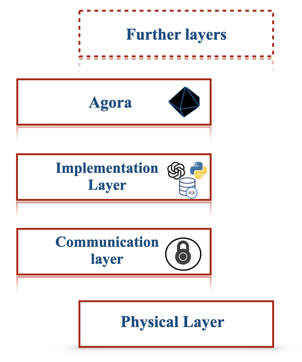
The image depicts a layered architecture diagram, illustrating a stack of layers representing different components of a system. The layers are arranged vertically, with the "Physical Layer" at the bottom and "Further layers" at the top. Each layer is contained within a rectangular box with rounded corners. Icons are present within some of the layers, presumably representing technologies or functionalities within those layers.
### Components/Axes
The diagram consists of the following layers, from bottom to top:
1. **Physical Layer:** Located at the bottom of the diagram.
2. **Communication layer:** Above the Physical Layer. Contains an icon resembling a network connection.
3. **Implementation Layer:** Above the Communication Layer. Contains two icons: a DNA helix and a database cylinder labeled "SQL".
4. **Agora:** Above the Implementation Layer. Contains a blue, multifaceted geometric shape.
5. **Further layers:** At the top of the diagram, enclosed in a dashed red rectangle.
There are no explicit axes or scales in this diagram. It's a conceptual representation of layers.
### Detailed Analysis or Content Details
* **Physical Layer:** No specific details or icons are present.
* **Communication layer:** Contains an icon that appears to represent network connectivity or communication protocols.
* **Implementation Layer:** Contains a DNA helix icon and a cylinder icon labeled "SQL". The DNA icon could represent biological or complex algorithmic processes, while the "SQL" icon clearly indicates a relational database component.
* **Agora:** Contains a blue, multifaceted geometric shape. The shape is difficult to identify precisely, but it could represent a complex data structure or a core component of the system.
* **Further layers:** This layer is indicated as being expandable, suggesting that the architecture can be extended with additional layers. The dashed red border indicates it is not a concrete layer but a placeholder for future development.
### Key Observations
The diagram illustrates a clear separation of concerns through its layered approach. The layers progress from the foundational "Physical Layer" to more abstract and application-specific layers like "Agora" and "Further layers". The inclusion of "SQL" in the "Implementation Layer" suggests that data persistence is a key aspect of the system. The icons provide visual cues about the technologies or functionalities within each layer.
### Interpretation
This diagram represents a typical layered architecture commonly used in software development. The layers abstract away complexity, allowing developers to focus on specific aspects of the system without needing to understand the intricacies of lower layers. The "Physical Layer" represents the underlying infrastructure, while the "Communication layer" handles data transfer. The "Implementation Layer" contains the core logic and data storage components. "Agora" likely represents a central processing or coordination component. The "Further layers" indicate the system's extensibility and potential for future growth.
The use of icons suggests a focus on specific technologies or functionalities within each layer. The diagram is a high-level overview and does not provide detailed information about the interactions between layers or the specific implementation details of each component. It serves as a conceptual model for understanding the system's architecture.