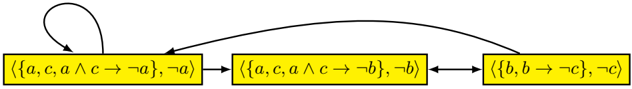
## Diagram: State Transition Diagram
### Overview
The image is a state transition diagram showing transitions between three states represented by yellow rectangular boxes. Each box contains a set of logical propositions. The transitions are indicated by black arrows.
### Components/Axes
* **States:** Three yellow rectangular boxes, each representing a state.
* **Transitions:** Black arrows indicating the transitions between states.
* **State Content:** Each state contains a set of logical propositions enclosed in curly braces `{}` and angle brackets `<>`.
### Detailed Analysis or ### Content Details
**State 1 (Leftmost):**
* Content: `<{a, c, a ∧ c → ¬a}, ¬a>`
* Self-loop: A curved arrow starts from the top of the box and loops back into the top of the same box, indicating a transition from the state to itself.
* Transition to State 2: A straight arrow points from the right side of State 1 to the left side of State 2.
* Transition from State 3: A curved arrow points from the right side of State 3 to the right side of State 1.
**State 2 (Middle):**
* Content: `<{a, c, a ∧ c → ¬b}, ¬b>`
* Transition from State 1: A straight arrow points from the right side of State 1 to the left side of State 2.
* Transition to State 3: A double-headed arrow points from the right side of State 2 to the left side of State 3.
**State 3 (Rightmost):**
* Content: `<{b, b → ¬c}, ¬c>`
* Transition from State 2: A double-headed arrow points from the right side of State 2 to the left side of State 3.
* Transition to State 1: A curved arrow points from the right side of State 3 to the right side of State 1.
### Key Observations
* State 1 has a self-loop, indicating it can transition back to itself.
* State 2 and State 3 have a bidirectional transition between them.
* State 3 transitions back to State 1.
### Interpretation
The diagram represents a state machine or a system that can exist in one of three states. The arrows indicate how the system can move between these states. The logical propositions within each state likely represent conditions or properties that hold true when the system is in that state. The transitions are triggered by events or conditions that cause the system to move from one state to another. The self-loop on State 1 suggests that the system can remain in that state under certain conditions. The bidirectional transition between State 2 and State 3 indicates a close relationship or dependency between these two states. The transition from State 3 back to State 1 completes a cycle in the state machine.