## Diagram: Block Configuration Transition
### Overview
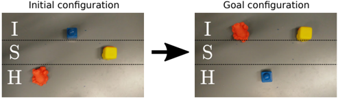
The image depicts a before-and-after comparison of block configurations across three labeled positions (I, S, H). Two states are shown: "Initial configuration" (left) and "Goal configuration" (right), connected by a black arrow indicating a transformation process.
### Components/Axes
- **Labels**:
- Vertical axis: Position identifiers "I" (top), "S" (middle), "H" (bottom)
- Horizontal axis: Two states ("Initial configuration", "Goal configuration")
- **Color Coding**:
- Blue block
- Yellow block
- Red block
- **Arrow**: Black arrow connecting initial to goal state
### Detailed Analysis
- **Initial Configuration**:
- Position I: Blue block
- Position S: Yellow block
- Position H: Red block
- **Goal Configuration**:
- Position I: Red block
- Position S: Yellow block (unchanged)
- Position H: Blue block
- **Color Movement**:
- Blue: Moves from I → H
- Red: Moves from H → I
- Yellow: Remains at S
### Key Observations
1. The yellow block maintains its position at S in both configurations
2. Blue and red blocks swap positions between I and H
3. No blocks are added/removed - only positional changes occur
4. The transformation preserves the total number of blocks (3)
### Interpretation
This diagram illustrates a positional permutation where two elements (blue/red blocks) exchange places while one (yellow) remains fixed. The unchanged yellow block at S suggests it serves as an anchor point or reference in the transformation process. The symmetrical swap between I and H positions implies a binary exchange mechanism, potentially representing:
- Data structure reorganization
- Resource allocation optimization
- State transition in a finite state machine
- Physical object rearrangement in a constrained system
The absence of intermediate steps suggests the transformation occurs in a single atomic operation. The preservation of block count while changing positions indicates a closed system with conserved elements but variable arrangements.