TECHNICAL ASSET FINGERPRINT
3a70ff194bb0697a791219e6
Click to view fullscreen
Press ESC or click to close
FOUND IN PAPERS
EXPERT: gemini-2.5-flash-free VERSION 1
RUNTIME: google-free/gemini-2.5-flash
INTEL_VERIFIED
## Diagram: Network Schematic with Special Components and Paths
### Overview
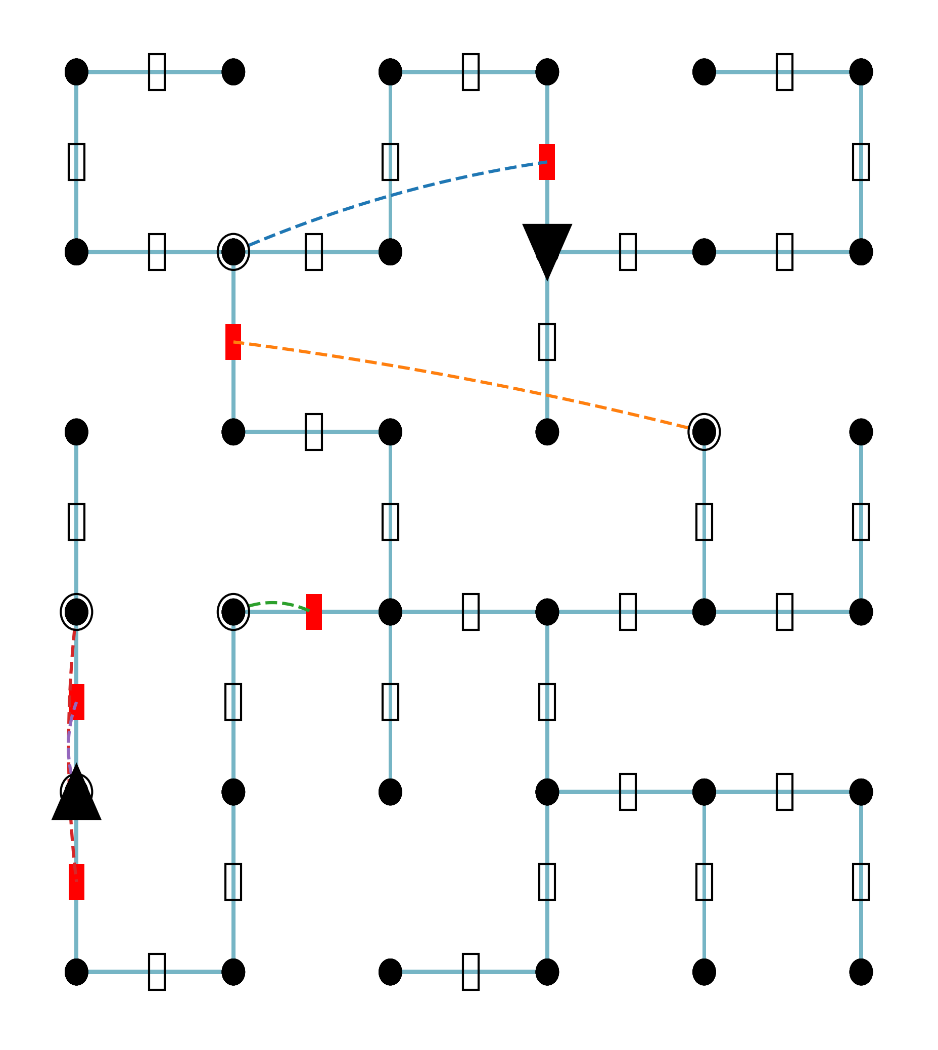
This image displays a schematic diagram representing a network structure composed of interconnected nodes and links. The network has a generally grid-like arrangement, with various standard and specialized components, as well as several distinct dashed lines indicating specific connections or paths. The diagram lacks explicit labels or a legend, requiring interpretation of the visual elements.
### Components/Axes
The diagram does not feature traditional axes or a legend with explicit labels. Instead, components are distinguished by their shape, fill, and outline.
**Primary Components:**
* **Nodes (Black Circles):** Represent connection points or junctions within the network. There are approximately 25 such nodes.
* **Links (Light Blue Lines):** Represent the connections or pathways between nodes. These form the backbone of the network.
* **Standard Link Components (White Rectangles with Black Outline):** Rectangular elements placed along light blue links, suggesting a standard component or state on that link. There are approximately 30 such components.
**Specialized Components:**
* **Special Nodes (Outlined Black Circles):** Black filled circles with a distinct white outline. These likely represent specific types of nodes, perhaps sources, destinations, or critical points. There are 4 such nodes:
* One in the top-left quadrant.
* One in the middle-left column.
* One in the bottom-middle-left area.
* One in the middle-right area.
* **Special Link Components (Red Rectangles):** Red filled rectangular elements placed along light blue links, indicating a distinct state or type of component on that link. There are 7 such components:
* One in the top-middle-right, on a vertical link.
* One in the top-middle-left, on a vertical link, below the top-left outlined node.
* One in the middle-left, on a vertical link, below the middle-left outlined node.
* One in the bottom-middle-left, on a horizontal link, to the right of the bottom-middle-left outlined node.
* Three in the far-left column, on vertical links (two above and one below the upward-pointing black triangle).
* **Special Nodes (Black Triangles):** Black filled triangular elements, likely indicating directional components, sources, or sinks. There are 2 such nodes:
* One downward-pointing triangle in the top-middle, on a vertical link.
* One upward-pointing triangle in the far-left column, on a vertical link.
**Special Paths/Connections (Dashed Lines):**
* **Blue Dashed Line:** A dashed line, light blue in color, indicating a specific connection or signal path.
* **Orange Dashed Line:** A dashed line, orange in color, indicating another specific connection or signal path.
* **Green Dashed Line:** A dashed line, green in color, indicating another specific connection or signal path.
* **Red Dashed Line:** A dashed line, red in color, indicating another specific connection or signal path.
* **Purple Dashed Line:** A dashed line, purple in color, indicating another specific connection or signal path.
### Detailed Analysis
The network is structured in an approximate 5x5 grid, though it is not perfectly uniform, with some edges and internal connections missing or modified.
**Grid Structure:**
* The network spans roughly 5 horizontal and 5 vertical "units" of nodes and links.
* The top row has 3 nodes and 2 horizontal links, forming a partial segment.
* The second row from the top has 5 nodes and 4 horizontal links.
* The third row from the top has 5 nodes and 4 horizontal links.
* The fourth row from the top has 5 nodes and 4 horizontal links.
* The bottom row has 3 nodes and 2 horizontal links, forming a partial segment.
* Vertical links connect nodes between rows, maintaining the grid-like appearance.
**Placement and Connectivity of Special Elements:**
1. **Top-Left Outlined Node:** Located in the top-left quadrant, it is connected to a standard node to its right via a horizontal link with a standard white rectangle component. It is also connected downwards to another standard node via a vertical link with a red rectangle component.
* **Blue Dashed Line:** Originates from this top-left outlined node, extends diagonally upwards and to the right, passing over a standard white rectangle component, and terminates at the red rectangle component located on a vertical link in the top-middle-right section of the diagram.
2. **Top-Middle-Left Red Rectangle:** This component is on a vertical link, directly below the node that is to the right of the top-left outlined node.
* **Orange Dashed Line:** Originates from this red rectangle, extends diagonally downwards and to the right, passing over a standard white rectangle component, and terminates at the middle-right outlined node.
3. **Top-Middle Downward-Pointing Triangle:** Located on a vertical link in the top-middle section, connected to a node above and a node below.
4. **Middle-Left Outlined Node:** Located in the far-left column, it is connected to a standard node to its right via a horizontal link with a standard white rectangle component. It is also connected downwards to a standard node via a vertical link.
* **Red Dashed Line:** Originates from this middle-left outlined node, extends vertically downwards, passing over a red rectangle component, and terminates at the upward-pointing black triangle in the far-left column.
* **Purple Dashed Line:** Originates from this same middle-left outlined node, extends vertically downwards, almost coincident with the red dashed line (slightly to its right), passing over the same red rectangle component, and also terminates at the upward-pointing black triangle.
5. **Upward-Pointing Black Triangle:** Located in the far-left column, it is connected to a node above (via a link with two red rectangles and the red/purple dashed lines) and a node below (via a link with one red rectangle).
6. **Bottom-Middle-Left Outlined Node:** Located in the bottom-middle-left area, it is connected to a standard node to its left via a horizontal link with a standard white rectangle component. It is also connected to a standard node to its right via a horizontal link.
* **Green Dashed Line:** Originates from this bottom-middle-left outlined node, extends horizontally to the right, and terminates at a red rectangle component located on the horizontal link immediately to its right.
7. **Middle-Right Outlined Node:** Located in the middle-right section, it is connected to a standard node to its left via a horizontal link with a standard white rectangle component. It is also connected downwards to a standard node via a vertical link with a standard white rectangle component.
### Key Observations
* The network exhibits a primary grid topology, suggesting a structured system.
* The presence of different component types (standard white rectangles, red rectangles, outlined circles, triangles) indicates functional diversity within the network.
* The dashed lines represent distinct, non-standard connections or signal paths that bypass or interact with the primary light blue links and components. These paths are colored differently (blue, orange, green, red, purple), suggesting different types of interactions or priorities.
* Several red rectangle components are involved in the start or end points of these dashed lines, or are traversed by them, implying they might be critical or "active" points.
* The upward-pointing and downward-pointing triangles suggest directional flow or specific input/output points.
* The co-occurrence of red and purple dashed lines between the same two points (middle-left outlined node and upward-pointing triangle) is notable, possibly indicating parallel signals, redundant paths, or different signal types along the same logical connection.
### Interpretation
This diagram likely represents a simplified model of a system where nodes are junctions or processing units, and links are communication channels or physical connections.
* **Standard Components (White Rectangles):** Could represent basic elements like resistors, switches, valves, or standard data packets/flow.
* **Special Nodes (Outlined Circles):** May denote critical points, control centers, specific devices, or points of interest for monitoring or intervention. Their involvement in initiating or terminating dashed lines reinforces their special status.
* **Special Link Components (Red Rectangles):** These could signify active components, faulty sections, high-priority links, or points where a specific action or transformation occurs. Their interaction with dashed lines suggests they are points of interaction for special signals or bypasses.
* **Triangles:** The downward-pointing triangle might represent a source or an input, while the upward-pointing triangle could be a sink, an output, or a measurement point. Their placement on vertical links suggests a flow direction.
* **Dashed Lines (Colored Paths):** These are crucial. They likely represent:
* **Alternative/Bypass Paths:** Connections that exist outside the primary grid structure.
* **Signal/Control Lines:** Non-physical connections, like wireless signals, control commands, or data flows that don't follow the main physical links.
* **Fault Paths/Propagation:** The spread of a fault or anomaly through the system.
* **Logical Connections:** Relationships between components that are not direct physical links.
* The different colors (blue, orange, green, red, purple) strongly suggest different types of signals, priorities, or functional categories for these special paths. The red and purple lines being almost identical could indicate two distinct but closely related signals or redundant control paths.
In essence, the diagram illustrates a network with a baseline structure and several overlaid "special" functionalities or states. The outlined nodes and red rectangles appear to be key interaction points for these special functions, and the dashed lines map out how these functions or signals propagate through or across the network. Without a legend, the exact domain (e.g., electrical circuit, water distribution, data network, process flow) remains ambiguous, but the visual language strongly implies a system with both standard operations and specific, highlighted operational modes or conditions.
DECODING INTELLIGENCE...