# Technical Diagram Analysis
## Diagram Overview
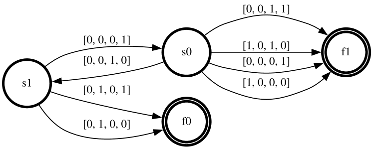
The image depicts a **state transition diagram** with three nodes (`S0`, `S1`, `I1`) and directional edges labeled with binary vectors. The diagram represents a finite state machine or automaton with transitions governed by 4-bit binary inputs.
---
## Node Definitions
1. **`S0`**
- Central node with **4 incoming edges** and **3 outgoing edges**.
- Acts as a hub for transitions between states.
2. **`S1`**
- Leftmost node with **2 incoming edges** and **2 outgoing edges**.
- Represents an intermediate state.
3. **`I1`**
- Rightmost node with **2 incoming edges** and **1 outgoing edge**.
- Likely a terminal or output state.
---
## Edge Labels and Transitions
All edges are labeled with 4-bit binary vectors. Below are the transitions:
### From `S0`:
- **To `S1`**:
- Label: `[0, 0, 0, 1]`
- Label: `[0, 0, 1, 0]`
- **To `I1`**:
- Label: `[0, 0, 1, 1]`
- Label: `[1, 0, 1, 0]`
### From `S1`:
- **To `I0`**:
- Label: `[0, 1, 0, 0]`
- Label: `[0, 1, 0, 1]`
### From `I1`:
- **To `S0`**:
- Label: `[1, 0, 0, 0]`
- Label: `[1, 0, 0, 1]`
---
## Flow Analysis
1. **`S0` → `S1`**:
- Transitions occur with inputs `[0,0,0,1]` and `[0,0,1,0]`.
- Suggests conditional branching based on the last two bits of the input.
2. **`S0` → `I1`**:
- Direct transitions with inputs `[0,0,1,1]` and `[1,0,1,0]`.
- Indicates immediate output state activation under specific conditions.
3. **`S1` → `I0`**:
- Transitions with inputs `[0,1,0,0]` and `[0,1,0,1]`.
- Output state `I0` is triggered when the second bit is `1`.
4. **`I1` → `S0`**:
- Feedback loop with inputs `[1,0,0,0]` and `[1,0,0,1]`.
- Enables resetting or re-initializing the system.
---
## Key Observations
- **Binary Input Structure**:
All transitions use 4-bit vectors, implying a system that processes 4-dimensional binary inputs (e.g., sensor data, control signals).
- **State Machine Behavior**:
- `S0` is the primary decision node, routing inputs to `S1`, `I1`, or back to itself.
- `I1` has a feedback mechanism to `S0`, suggesting cyclical operations.
- `I0` is a terminal state with no outgoing edges, acting as an endpoint.
- **Symmetry in Labels**:
Labels like `[0,0,1,1]` and `[1,0,1,0]` suggest patterns where specific bit positions (e.g., third and fourth bits) determine transitions.
---
## Diagram Structure
- **Nodes**:
- `S0` (central), `S1` (left), `I1` (right).
- **Edges**:
- Directed arrows with binary labels.
- No self-loops except for `S0` → `S0` (implied by feedback from `I1`).
---
## Missing Elements
- **Legend**: Not explicitly present in the diagram.
- **Axis Titles/Labels**: Not applicable (diagram, not a chart).
- **Data Table**: No tabular data included.
---
## Conclusion
This diagram models a finite state machine with 3 states (`S0`, `S1`, `I1`) and 7 transitions governed by 4-bit binary inputs. The system exhibits conditional routing, feedback loops, and terminal states, likely used in digital logic, control systems, or computational models.