## Diagram: Finite State Automaton
### Overview
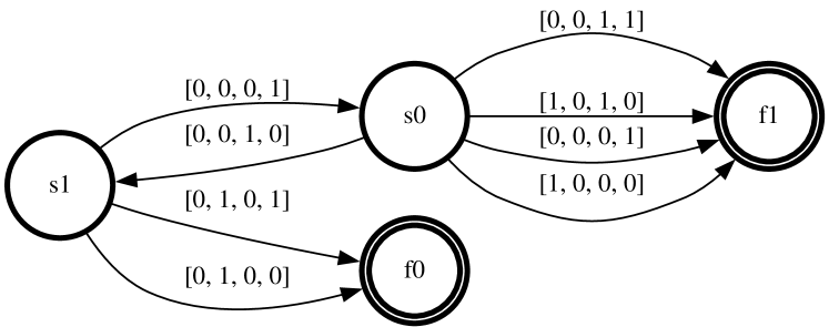
The image depicts a finite state automaton (FSA) diagram. It consists of four states represented by circles, labeled as "s1", "s0", "s2", and "s3". The states are connected by directed edges (arrows) labeled with binary strings, indicating the transitions between states based on input. States "s2" and "s3" are accepting states, indicated by double circles.
### Components/Axes
* **States:**
* s1 (single circle) - Start state (located on the left)
* s0 (single circle) - Intermediate state (located in the center)
* s2 (double circle) - Accepting state (located on the right)
* s3 (double circle) - Accepting state (located at the bottom center)
* **Transitions:** Directed arrows connecting the states, labeled with binary strings.
* **Labels:** Binary strings labeling the transitions, such as "|0,0,0,1|", "|0,0,1,0|", "|0,1,0,1|", "|0,1,0,0|", "|1,0,1,0|", "|1,0,0,0|", "|1,0,0,1|".
### Detailed Analysis
* **State s1:**
* Transitions to s0 with input "|0,0,0,1|".
* Transitions to s0 with input "|0,0,1,0|".
* Transitions to s1 with input "|0,1,0,1|".
* Transitions to s3 with input "|0,1,0,0|".
* **State s0:**
* Transitions to s2 with input "|1,0,1,0|".
* Transitions to s2 with input "|0,0,0,1|".
* **State s2:**
* Transitions to s2 with input "|0,0,1,1|".
* **State s3:** No outgoing transitions.
### Key Observations
* States s2 and s3 are accepting states.
* State s1 has self-loop transition.
* State s3 has no outgoing transitions.
### Interpretation
The diagram represents a finite state automaton that accepts strings based on the transitions between states. The automaton starts at state s1. If the automaton reaches either state s2 or s3, the input string is accepted. The binary strings on the transitions define the input sequences that cause the automaton to move from one state to another. The automaton appears to recognize specific patterns of binary inputs, leading to acceptance or rejection of the input string.