## Diagram: Exploded View of a Multi-Layered Modular System
### Overview
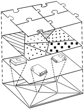
The image is a black-and-white technical line drawing illustrating an exploded view of a four-layered structure. The diagram demonstrates how different functional layers stack and interact, with a focus on modular components and their spatial relationships. There is no textual information, labels, or numerical data present in the image.
### Components/Axes
The diagram is composed of four distinct horizontal layers, shown separated vertically to reveal their individual structures and connections.
1. **Top Layer (Layer 1):** A surface composed of interlocking, puzzle-like pieces. The pieces have irregular, curved edges, suggesting a custom-fit, seamless assembly.
2. **Second Layer (Layer 2):** A layer divided into distinct patterned regions. From left to right, the visible patterns are:
* A region with diagonal hatching lines.
* A region with a dense dot pattern.
* A region with a sparse dot pattern.
* A region with a grid of small squares.
3. **Third Layer (Layer 3):** Contains three discrete, three-dimensional rectangular modules or components. They are positioned above specific areas of the layer below.
4. **Bottom Layer (Layer 4):** A base layer structured as a triangulated mesh or grid, forming a geometric, faceted surface.
**Spatial Relationships & Flow:**
* Dashed lines project downward from the three modules in Layer 3 to specific triangular facets within the mesh of Layer 4. This visually maps each component to a designated area on the base.
* The exploded view implies a vertical assembly sequence: the patterned Layer 2 sits atop the component Layer 3, which in turn interfaces with the structural base Layer 4. The puzzle-piece Layer 1 forms the final top surface.
### Detailed Analysis
* **Layer 1 (Puzzle Surface):** Composed of at least five visible interlocking pieces. The seams are curved, not straight, indicating a design meant to lock together securely without visible fasteners.
* **Layer 2 (Patterned Layer):** The different patterns (hatching, dots, squares) likely represent different material properties, functional zones, or surface treatments within a single planar layer.
* **Layer 3 (Components):** The three modules are drawn as simple rectangular boxes with slight 3D perspective. Their identical shape suggests they are standardized units. Their placement is not symmetrical; one is left-of-center, one is central, and one is right-of-center.
* **Layer 4 (Triangulated Base):** The mesh is composed of interconnected triangles of varying sizes and shapes. This is a common structural design for strength and load distribution. The dashed lines connect each module to a cluster of triangles, suggesting each module supports or interacts with a specific zone of the base.
### Key Observations
1. **Hierarchical Abstraction:** The diagram moves from a complex, organic top surface (puzzle pieces) through functional zones (patterns) and discrete components, down to a fundamental geometric structure (triangulated mesh).
2. **Modularity:** The presence of identical components and the puzzle-like top layer strongly emphasizes a design philosophy based on interchangeable or custom-fit modules.
3. **Interface Mapping:** The dashed lines are the only explicit relational indicators, creating a clear one-to-many mapping between each module and a specific region of the foundational structure.
### Interpretation
This diagram is a conceptual representation of a **modular, layered system architecture**. It is not a blueprint for a specific object but rather an illustration of a design principle.
* **What it suggests:** The system is built from the ground up on a stable, triangulated foundation (Layer 4). Specific functional modules (Layer 3) are mounted to this foundation, each responsible for a defined zone. Above these modules sits a layer (Layer 2) that may represent different material interfaces, sensor arrays, or functional surfaces, each with distinct properties (indicated by patterns). The entire assembly is capped by a seamless, custom-fitted surface (Layer 1).
* **How elements relate:** The flow is vertical and integrative. The base provides structure, the modules provide core function, the patterned layer mediates or specializes that function, and the top layer provides a unified, finished interface. The dashed lines are critical, showing that the modules are not floating but are anchored to and service specific parts of the underlying structure.
* **Potential Applications:** This model could abstractly represent anything from a multi-layered PCB (printed circuit board) with components and solder mask, to a architectural facade system with structural supports, cladding panels, and a finish layer, or even a conceptual model for a data processing stack where each layer represents a different level of data abstraction.
* **Notable Anomaly:** The complete absence of text, labels, or a legend is significant. It indicates the diagram is meant to convey a **conceptual relationship** rather than specific technical specifications. The understanding is derived purely from the visual metaphor of layers, modules, and connections.