TECHNICAL ASSET FINGERPRINT
3b8d835bbcaca54f5cc1c8aa
Click to view fullscreen
Press ESC or click to close
FOUND IN PAPERS
EXPERT: healer-alpha-free VERSION 1
RUNTIME: free/openrouter/healer-alpha
INTEL_VERIFIED
\n
## Diagram: Transformer Model Quantization Framework
### Overview
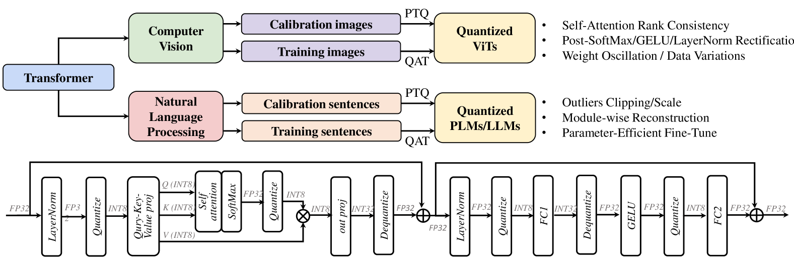
The image is a technical diagram illustrating a framework for quantizing Transformer-based models, split into two distinct sections. The top section is a high-level flowchart showing the quantization process for two major application domains: Computer Vision and Natural Language Processing. The bottom section is a detailed architectural diagram of a quantized Transformer block, showing the specific sequence of operations and data type conversions (FP32 to INT8 and back).
### Components/Axes
The diagram contains no traditional chart axes or legends. Its components are labeled blocks, arrows indicating data flow, and textual annotations.
**Top Flowchart Components:**
1. **Root Block:** "Transformer" (blue rectangle, left-center).
2. **Domain Branches:**
* "Computer Vision" (light green rectangle, top-left).
* "Natural Language Processing" (pink rectangle, bottom-left).
3. **Data Blocks (for each domain):**
* "Calibration images" / "Calibration sentences" (light purple/peach rectangles).
* "Training images" / "Training sentences" (light purple/peach rectangles).
4. **Quantization Method Labels:** "PTQ" (Post-Training Quantization) and "QAT" (Quantization-Aware Training) are written on the arrows leading to the output blocks.
5. **Output Blocks:**
* "Quantized ViTs" (Vision Transformers) (yellow rectangle, top-right).
* "Quantized PLMs/LLMs" (Pre-trained Language Models/Large Language Models) (yellow rectangle, bottom-right).
6. **Bullet Point Lists (to the right of each output block):**
* For **Quantized ViTs**:
* Self-Attention Rank Consistency
* Post-SoftMax/GELU/LayerNorm Rectification
* Weight Oscillation / Data Variations
* For **Quantized PLMs/LLMs**:
* Outliers Clipping/Scale
* Module-wise Reconstruction
* Parameter-Efficient Fine-Tune
**Bottom Architecture Diagram Components (Left to Right Flow):**
The diagram shows a sequential pipeline with residual connections. Each major operation is in a rounded rectangle. Data types (FP32, INT8) are labeled on the connecting arrows.
1. **Input:** "FP32" data enters.
2. **First Sub-block (Attention):**
* `LayerNorm` (FP32 -> FP32)
* `Quantize` (FP32 -> INT8)
* `Query-Key-Value proj` (INT8 -> Q/K/V in INT8)
* `Self attention` & `SoftMax` (INT8 -> FP32)
* `Quantize` (FP32 -> INT8)
* `out proj` (INT8 -> INT32)
* `Dequantize` (INT32 -> FP32)
* **Residual Connection:** Adds the original FP32 input to the output of `Dequantize`.
3. **Second Sub-block (Feed-Forward):**
* `LayerNorm` (FP32 -> FP32)
* `Quantize` (FP32 -> INT8)
* `FC1` (Fully Connected 1) (INT8 -> INT32)
* `Dequantize` (INT32 -> FP32)
* `GELU` (activation function) (FP32 -> FP32)
* `Quantize` (FP32 -> INT8)
* `FC2` (Fully Connected 2) (INT8 -> FP32)
* **Residual Connection:** Adds the output from the first sub-block's residual to the output of `FC2`.
4. **Output:** "FP32" data exits.
### Detailed Analysis
**Flow and Relationships:**
The top flowchart establishes that the quantization framework is domain-aware. It takes a generic "Transformer" and applies specialized techniques depending on whether it's for vision (ViTs) or language (PLMs/LLMs). The process uses both calibration data (for PTQ) and training data (for QAT).
The bottom diagram details the *how* of quantization within a single Transformer block. It reveals a pattern of quantizing activations (to INT8) before compute-heavy operations (like projections, attention, FC layers) and dequantizing the results (to FP32) for operations that require higher precision (like SoftMax, GELU, LayerNorm, and residual additions). The data type transitions are meticulously labeled: FP32 -> INT8 (Quantize), INT8 -> INT32 (during computation), INT32 -> FP32 (Dequantize).
**Spatial Grounding:**
* The "Computer Vision" branch is positioned above the "Natural Language Processing" branch.
* The bullet-point techniques are aligned to the right of their respective "Quantized" output blocks.
* The detailed architecture diagram spans the entire bottom half of the image, flowing strictly left-to-right. The two residual connections are shown as lines arching over the main computational blocks.
### Key Observations
1. **Domain-Specific Strategies:** The framework explicitly lists different core challenges/techniques for quantizing vision models (e.g., "Self-Attention Rank Consistency") versus language models (e.g., "Outliers Clipping/Scale").
2. **Hybrid Precision Pipeline:** The architecture does not quantize everything to INT8 uniformly. It uses a mix of FP32, INT8, and INT32, strategically placing quantization and dequantization steps around specific operations to balance efficiency and accuracy.
3. **Focus on Activation Quantization:** The detailed diagram primarily shows the quantization of *activations* (the data flowing between layers), as indicated by the `Quantize`/`Dequantize` blocks on the main path. Weight quantization is implied but not explicitly diagrammed in this view.
4. **Preservation of Residual Paths:** The residual connections (the `⊕` symbols) operate in FP32, suggesting that the high-precision addition is critical for maintaining model performance.
### Interpretation
This diagram serves as a technical blueprint for efficiently deploying Transformer models. It communicates two key messages:
1. **Strategic Abstraction:** Quantization is not a one-size-fits-all process. The top chart argues that effective quantization requires understanding the unique statistical properties and failure modes of the model's application domain (vision vs. language). The listed bullet points are likely the titles of specific methods or research papers addressing these domain-specific issues.
2. **Operational Precision:** The bottom diagram reveals the engineering precision required. It shows that quantization is a careful dance of data type conversion. The goal is to confine lower-precision (INT8) math to the most computationally expensive parts (matrix multiplications in projections and FC layers) while maintaining higher precision (FP32) for sensitive non-linear functions (SoftMax, GELU) and normalization. This hybrid approach aims to achieve the speed and memory benefits of integer arithmetic without catastrophic loss of model accuracy.
In essence, the image bridges high-level methodology (domain-aware quantization) with low-level implementation (mixed-precision tensor operations), providing a comprehensive view of the challenges and solutions in making massive Transformer models more efficient.
DECODING INTELLIGENCE...