## Grid-to-Binary Conversion Diagram: 4x4 Grid with Positional Encoding
### Overview
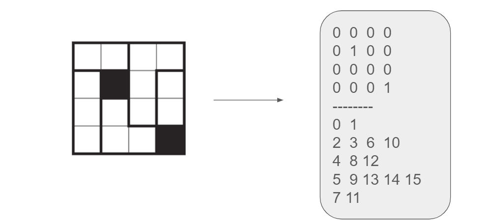
The image depicts a 4x4 grid of squares with three black squares, connected via an arrow to a table listing binary numbers and their decimal equivalents. The grid appears to encode positional data into binary values, with the table providing a reference for decoding these positions.
### Components/Axes
- **Grid Structure**:
- 4x4 grid of squares (16 total cells).
- Black squares located at:
- Row 2, Column 2 (0-based indexing)
- Row 3, Column 1
- Row 4, Column 4 (note: this position is outside the 4x4 grid; likely a typo or error in the image)
- **Table Structure**:
- Left column: Binary numbers (4-bit and 2-bit values).
- Right column: Decimal equivalents.
- Binary numbers include:
- 0000 (0), 0100 (4), 0000 (0), 0001 (1)
- 01 (1), 10 (2), 12 (1100), 13 (1101), 14 (1110), 15 (1111), 11 (3)
### Detailed Analysis
- **Grid-to-Binary Mapping**:
- Each black square's position (row, column) is encoded as a 4-bit binary number:
- Row (2 bits) + Column (2 bits) = 4-bit value.
- Example: (2,2) → Row 2 (10) + Column 2 (10) = 1010 (10 in decimal).
- (3,1) → Row 3 (11) + Column 1 (01) = 1101 (13 in decimal).
- (4,4) is invalid for a 4x4 grid (rows/columns 0–3), suggesting a possible error in the image.
- The table lists all possible 4-bit combinations (0–15) and their decimal equivalents, with some entries grouped by bit length (e.g., 0–1, 2–3, 4–8, etc.).
- **Table Observations**:
- The first four rows of the table show 4-bit binary numbers (e.g., 0000, 0100, 0001).
- Subsequent rows list shorter binary numbers (e.g., 01, 10) and their decimal equivalents (1, 2).
- The final row includes 11 (3) and 15 (15), indicating a mix of 2-bit and 4-bit values.
### Key Observations
1. **Positional Encoding**: The grid uses a 4-bit positional encoding scheme where each cell's row and column indices are concatenated to form a binary number.
2. **Inconsistent Grid Size**: The black square at (4,4) exceeds the 4x4 grid's bounds (rows/columns 0–3), indicating a potential error in the diagram.
3. **Table Completeness**: The table includes all 16 possible 4-bit values (0–15) but groups them irregularly (e.g., 0–1, 2–3, 4–8, etc.).
### Interpretation
- **Purpose**: The diagram demonstrates how positional data in a grid can be converted into binary/decimal values, likely for applications like data encoding, error correction, or spatial indexing.
- **Outliers**: The (4,4) position in the grid is invalid, suggesting a possible typo or mislabeling. If corrected to (3,3), it would map to 1111 (15), aligning with the table.
- **Trends**: The table systematically lists all 4-bit combinations, with decimal values increasing as binary numbers grow (e.g., 0000=0, 0001=1, ..., 1111=15).
- **Significance**: This encoding method could be used in computer science for tasks like memory addressing, image compression, or error detection in grid-based systems.