## Circuit Diagram: Memristor-Based Neural Network
### Overview
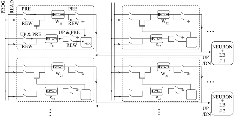
The image is a circuit diagram depicting a memristor-based neural network architecture. It shows a 2x2 array of memristor cells, along with associated circuitry for programming (PROG), reading (READ), precharging (PRE), and rewriting (REW). The diagram also illustrates the connection to neuron blocks (NEURON + LB). The diagram is repeated with ellipsis to indicate that the array can be expanded.
### Components/Axes
* **Vertical Axis (Left):**
* PROG: Programming line
* READ: Read line
* **Memristor Cells:**
* W11, W12, W21, W22: Memristors representing synaptic weights.
* e11, e12, e21, e22: Memristors representing error signals.
* **Control Signals:**
* PRE: Precharge signal
* REW: Rewrite signal
* UP & PRE: Update and Precharge signal
* **Neuron Blocks (Right):**
* NEURON + LB #1: Neuron and Learning Block 1
* NEURON + LB #2: Neuron and Learning Block 2
* **Other Components:**
* VPROG: Programming voltage source
* Switches: Various switches controlling the flow of current for different operations.
* Ground: Ground connections.
* **Interconnections:**
* Horizontal lines: Connect memristor cells to control signals and neuron blocks.
* Vertical lines: Connect memristor cells to programming and read lines.
* UP/DN: Update/Down signal lines connecting to neuron blocks.
### Detailed Analysis
The diagram shows a 2x2 array of memristor cells. Each cell consists of two memristors, one representing the synaptic weight (W) and the other representing the error signal (e). The cells are arranged in a grid, with the synaptic weights (W11, W12, W21, W22) located above the error signals (e11, e12, e21, e22) in each cell.
Each memristor cell is connected to a set of control signals (PRE, REW, UP & PRE) and to the programming and read lines (PROG, READ). The control signals are used to configure the cell for different operations, such as programming, reading, precharging, and rewriting.
The memristor cells are also connected to neuron blocks (NEURON + LB). The neuron blocks receive the output of the memristor cells and perform the necessary computations to update the synaptic weights.
The diagram also shows a programming voltage source (VPROG), which is used to program the memristor cells. The programming voltage is applied to the memristor cells through a set of switches.
The diagram includes ellipsis (...) to indicate that the array can be expanded to larger sizes.
* **Top-Left Cell:** Contains memristor W11, memristor e11, and associated switches. Control signals PRE, REW, and UP & PRE are connected to this cell.
* **Top-Right Cell:** Contains memristor W12, memristor e12, and associated switches. Control signals PRE, REW, and UP & PRE are connected to this cell.
* **Bottom-Left Cell:** Contains memristor W21, memristor e21, and associated switches.
* **Bottom-Right Cell:** Contains memristor W22, memristor e22, and associated switches.
* **Neuron Blocks:** Two neuron blocks are shown, labeled NEURON + LB #1 and NEURON + LB #2. These blocks receive input from the memristor cells and provide update signals (UP/DN).
### Key Observations
* The diagram illustrates a basic architecture for a memristor-based neural network.
* The memristor cells are arranged in a grid, with each cell containing two memristors.
* The memristor cells are connected to control signals, programming and read lines, and neuron blocks.
* The diagram includes a programming voltage source and various switches for controlling the flow of current.
* The array can be expanded to larger sizes.
### Interpretation
The diagram demonstrates a hardware implementation of a neural network using memristors. Memristors are used to represent synaptic weights and error signals, allowing for efficient storage and computation. The control signals and switches enable precise control over the programming, reading, and updating of the memristor cells. The neuron blocks perform the necessary computations to update the synaptic weights based on the error signals. This architecture has the potential to enable the development of energy-efficient and high-performance neural networks. The use of memristors allows for in-memory computing, which can significantly reduce the energy consumption of neural networks. The ability to expand the array to larger sizes allows for the creation of more complex neural networks.