## Diagram: Relationship Flow Model
### Overview
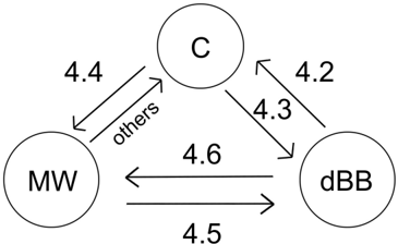
The image is a directed graph diagram illustrating bidirectional relationships between three distinct entities labeled "C", "MW", and "dBB". The diagram uses arrows to indicate the direction of the relationship between nodes, with each path labeled by a numerical identifier or a text descriptor, likely referencing specific sections in a technical document.
### Components/Axes
* **Nodes:** Three circular nodes arranged in a triangular formation:
* **C:** Positioned at the top center.
* **MW:** Positioned at the bottom left.
* **dBB:** Positioned at the bottom right.
* **Edges:** Six directed arrows representing the relationships between the nodes.
* **Labels:** Numerical identifiers (4.2, 4.3, 4.4, 4.5, 4.6) and the text "others".
### Detailed Analysis
The diagram depicts a fully connected graph where every node has a bidirectional relationship with the other two nodes.
**1. Relationship between C and MW:**
* **C to MW:** An arrow points from C (top) to MW (bottom-left). It is labeled **4.4**.
* **MW to C:** An arrow points from MW (bottom-left) to C (top). It is labeled **others**.
**2. Relationship between C and dBB:**
* **dBB to C:** An arrow points from dBB (bottom-right) to C (top). It is labeled **4.2**.
* **C to dBB:** An arrow points from C (top) to dBB (bottom-right). It is labeled **4.3**.
**3. Relationship between MW and dBB:**
* **dBB to MW:** An arrow points from dBB (bottom-right) to MW (bottom-left). It is labeled **4.6**.
* **MW to dBB:** An arrow points from MW (bottom-left) to dBB (bottom-right). It is labeled **4.5**.
### Key Observations
* **Sequential Numbering:** The numerical labels follow a sequential pattern (4.2, 4.3, 4.4, 4.5, 4.6), suggesting these numbers correspond to specific subsections within a larger technical document or specification.
* **Anomaly:** The relationship from "MW" to "C" is the only one not labeled with a number, instead using the text "others". This implies that this specific relationship might be a catch-all category, defined elsewhere, or not covered by the specific numbered sections of the source document.
* **Symmetry:** The diagram is perfectly symmetrical in its connectivity; every node interacts with every other node in both directions.
### Interpretation
This diagram functions as a navigational map or a summary of interdependencies between three distinct concepts or modules (C, MW, and dBB).
* **Document Referencing:** The most likely interpretation is that this is a figure from a technical paper or manual. The numbers (4.2–4.6) are almost certainly cross-references to specific sections of the text that detail the nature of the interaction between these entities.
* **The "Others" Outlier:** The use of the label "others" for the MW-to-C path is significant. It suggests that while the other five relationships are explicitly defined and documented within the numbered sections of the source material, the MW-to-C relationship is either a default state, a miscellaneous category, or an interaction that does not warrant its own dedicated section.
* **System Architecture:** If these represent system components, the diagram demonstrates a highly coupled system where all components are interdependent. The specific numbering suggests a hierarchical or sequential explanation of these dependencies.