## Diagram: Graph Transformation via Vertex Identification
### Overview
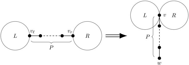
The image depicts a two-stage diagram illustrating a graph transformation process. On the left is an initial state with two separate components connected by a path. An arrow points to the right, showing the resulting state after a transformation where the two components are merged at a single vertex, and the connecting path is reattached.
### Components/Axes
The diagram is composed of two primary sections separated by a transformation arrow.
**Left Section (Initial State):**
* **Component L:** A circle labeled with the capital letter "L".
* **Component R:** A circle labeled with the capital letter "R".
* **Path P:** A dashed line connecting the two circles. It is labeled with a capital "P" underneath a curly brace that spans its length.
* **Vertices:**
* `v_l`: A solid black dot on the circumference of circle L, marking the left endpoint of path P.
* `v_r`: A solid black dot on the circumference of circle R, marking the right endpoint of path P.
* Two additional unlabeled solid black dots are shown along the dashed path between `v_l` and `v_r`, indicating intermediate vertices.
**Transformation Arrow:**
* A thick, black arrow points from the left section to the right section, indicating the direction of the transformation.
**Right Section (Transformed State):**
* **Merged Components L and R:** The two circles are now tangent, touching at a single point.
* **Vertex v:** A solid black dot at the point of tangency between circles L and R. This vertex is labeled with a lowercase "v".
* **Path P:** The same dashed line, now originating from vertex `v` and extending vertically downward. It is again labeled with a capital "P" next to a curly brace spanning its length.
* **Vertex w:** A solid black dot at the bottom endpoint of the vertical path P, labeled with a lowercase "w".
* **Intermediate Vertices:** Two additional unlabeled solid black dots are shown along the vertical dashed path between `v` and `w`.
### Detailed Analysis
The diagram illustrates a specific graph operation:
1. **Initial Configuration:** Two distinct graph components (represented by circles L and R) are connected by a path `P`. This path has distinct endpoints `v_l` (in L) and `v_r` (in R).
2. **Transformation:** The arrow signifies an operation where the vertices `v_l` and `v_r` are identified (merged) into a single vertex `v`. This operation joins the two previously separate components L and R into one connected component.
3. **Resulting Configuration:** After the merge, the original path `P` is now attached to the new merged vertex `v`. Its other endpoint is labeled `w`. The path `P` is depicted as hanging vertically from `v`.
### Key Observations
* **Spatial Grounding:** The legend/labels (`L`, `R`, `P`, `v_l`, `v_r`, `v`, `w`) are placed directly adjacent to their corresponding graphical elements. The curly braces for `P` are positioned centrally along the path's length in both stages.
* **Visual Consistency:** The graphical representation of the path `P` (dashed line with solid dot vertices) is consistent before and after the transformation, reinforcing that it is the same subgraph being relocated.
* **Topological Change:** The primary change is topological: two connected components become one. The circles L and R change from being disjoint to touching.
* **Vertex Relabeling:** The endpoints `v_l` and `v_r` cease to exist as distinct entities and are replaced by the single vertex `v`. A new endpoint `w` is introduced for the path in the transformed state.
### Interpretation
This diagram is a formal representation of a **vertex identification** or **edge contraction** operation in graph theory. It demonstrates how merging two vertices (`v_l` and `v_r`) that belong to different components (`L` and `R`) can unify the graph's structure.
The operation has significant implications:
* **Connectivity:** It reduces the number of connected components in the graph from two to one.
* **Path Preservation:** The path `P` is preserved but its attachment point changes from two distinct vertices to a single vertex. This could model scenarios like merging two network nodes and rerouting their connecting link.
* **Abstraction:** The use of circles for `L` and `R` suggests they may represent larger subgraphs or sets of vertices, not just single nodes. The transformation shows how a connection between two complex modules can be simplified to a single junction point.
The diagram serves as a clear, abstract visual proof or definition of this graph operation, emphasizing the change in connectivity and vertex relationships without specifying the internal structure of `L`, `R`, or the full path `P`.