## Current-Voltage and Time Dependence Charts
### Overview
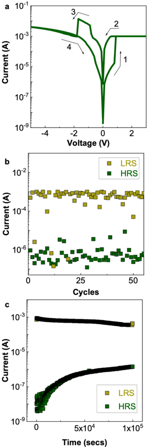
The image presents three charts (a, b, c) illustrating the electrical characteristics of a device, likely a memristor or similar resistive switching element. Chart (a) shows the current-voltage (I-V) characteristics, exhibiting hysteresis. Chart (b) displays the current levels for Low Resistance State (LRS) and High Resistance State (HRS) over multiple cycles. Chart (c) shows the current levels for LRS and HRS over time.
### Components/Axes
**Chart a: Current vs. Voltage**
* **Y-axis:** Current (A), logarithmic scale from 10^-9 to 10^-1.
* **X-axis:** Voltage (V), linear scale from -4 to 2.
* **Data:** A single curve showing the I-V relationship with hysteresis. Arrows indicate the direction of voltage sweep. The curve is green.
* **Annotations:** Numbers 1, 2, 3, and 4 indicate different segments of the voltage sweep cycle.
**Chart b: Current vs. Cycles**
* **Y-axis:** Current (A), logarithmic scale from 10^-6 to 10^-2.
* **X-axis:** Cycles, linear scale from 0 to 50.
* **Data:** Two scatter plots representing LRS and HRS currents over cycles.
* LRS: Data points are light yellow-green squares.
* HRS: Data points are dark green squares.
* **Legend:** Located at the top-right of the chart.
* LRS (light yellow-green square)
* HRS (dark green square)
**Chart c: Current vs. Time**
* **Y-axis:** Current (A), logarithmic scale from 10^-9 to 10^-3.
* **X-axis:** Time (secs), linear scale from 0 to 1x10^5 (100,000).
* **Data:** Two curves representing LRS and HRS currents over time.
* LRS: Data points are light yellow-green squares.
* HRS: Data points are dark green squares.
* **Legend:** Located at the top-right of the chart.
* LRS (light yellow-green square)
* HRS (dark green square)
### Detailed Analysis
**Chart a: Current vs. Voltage**
* The I-V curve starts at approximately (0V, 10^-7 A) and follows the path indicated by the arrows.
* Segment 1: As voltage increases from 0V to approximately 1V, the current increases to approximately 10^-3 A.
* Segment 2: The current remains relatively constant at approximately 10^-3 A as the voltage increases from 1V to 2V.
* Segment 3: As the voltage decreases from 2V to -2V, the current initially remains at approximately 10^-3 A, then drops sharply to approximately 10^-6 A around -1V.
* Segment 4: As the voltage decreases from -2V to -4V, the current remains relatively constant at approximately 10^-3 A. As the voltage increases from -4V to 0V, the current increases from approximately 10^-3 A to approximately 10^-7 A.
**Chart b: Current vs. Cycles**
* The LRS current (light yellow-green squares) fluctuates around 10^-3 A.
* The HRS current (dark green squares) fluctuates around 10^-6 A.
* There is a clear separation between the LRS and HRS current levels.
**Chart c: Current vs. Time**
* The LRS current (light yellow-green squares) starts at approximately 10^-3 A and decreases slightly over time to approximately 5*10^-4 A.
* The HRS current (dark green squares) starts at approximately 10^-8 A and increases significantly over time to approximately 10^-6 A.
### Key Observations
* **Hysteresis:** Chart (a) clearly shows hysteresis in the I-V characteristics, indicating resistive switching behavior.
* **Stable LRS:** In chart (b), the LRS current remains relatively stable over multiple cycles.
* **Unstable HRS:** In chart (b), the HRS current fluctuates more significantly than the LRS current.
* **Time Dependence:** Chart (c) shows that the HRS current increases significantly over time, while the LRS current decreases slightly.
### Interpretation
The data suggests that the device exhibits resistive switching behavior, with a clear difference between the LRS and HRS current levels. The hysteresis in the I-V curve confirms this behavior. The stability of the LRS current over cycles indicates good endurance. However, the increase in HRS current over time suggests that the device may be drifting towards the LRS, which could be a reliability concern. The device's resistance changes depending on the applied voltage and the duration of the applied voltage. The device's resistance also changes over time.