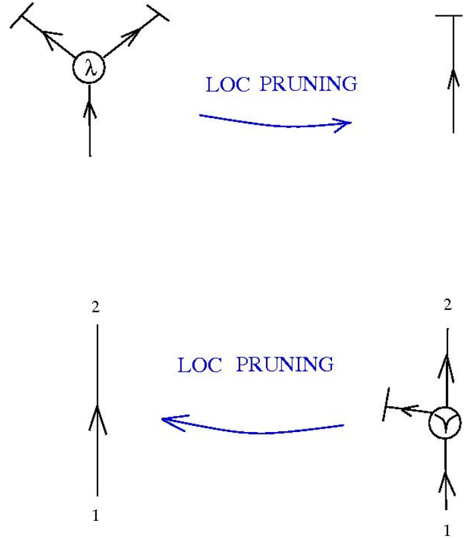
## Diagram: LOC Pruning Transformations
### Overview
The image depicts two diagrams illustrating "LOC PRUNING" transformations. Each diagram shows a transformation from a more complex structure to a simpler one, indicated by a curved arrow labeled "LOC PRUNING". The diagrams involve lines, arrows indicating direction, and circles containing symbols.
### Components/Axes
* **Diagram 1 (Top)**:
* A central node (circle) containing the symbol "λ".
* Three lines emanating from the node. Two lines point upwards and outwards, each terminating with a short perpendicular line. One line points downwards. All three lines have arrows indicating direction away from the central node.
* A single vertical line with an upward-pointing arrow and a short perpendicular line at the top.
* A curved arrow labeled "LOC PRUNING" pointing from the complex structure to the single line.
* **Diagram 2 (Bottom)**:
* A single vertical line with an upward-pointing arrow, labeled "1" at the bottom and "2" at the top.
* A node (circle) containing the symbol "Y".
* Three lines connected to the node. One line points downwards, labeled "1" at the bottom. One line points upwards, labeled "2" at the top. One line points to the left, terminating with a short perpendicular line. All three lines have arrows indicating direction away from the central node.
* A curved arrow labeled "LOC PRUNING" pointing from the complex structure to the single line.
### Detailed Analysis
* **Diagram 1**:
* The central node has three outgoing lines. The two upper lines are terminated with a short perpendicular line, indicating an external connection or constraint.
* The "LOC PRUNING" transformation simplifies this structure to a single outgoing line.
* **Diagram 2**:
* The single line is labeled with "1" at the bottom and "2" at the top, indicating a direction or flow from 1 to 2.
* The complex structure has a node with three outgoing lines. The left line is terminated with a short perpendicular line.
* The "LOC PRUNING" transformation simplifies this structure to a single line with the same directionality.
### Key Observations
* Both diagrams illustrate a simplification process labeled "LOC PRUNING".
* The complex structures involve nodes with three outgoing lines, one or more of which are terminated with a short perpendicular line.
* The simplified structures are single lines with a defined direction.
### Interpretation
The diagrams likely represent a simplification or reduction process in a system or model. "LOC PRUNING" seems to be a method for reducing complex structures to simpler, linear representations. The short perpendicular lines may indicate external constraints or connections that are removed during the pruning process. The symbols "λ" and "Y" within the nodes might represent specific types of nodes or operations being simplified. The numbers "1" and "2" in the second diagram likely represent input and output, or a direction of flow.