\n
## Diagram: LOC Pruning Illustration
### Overview
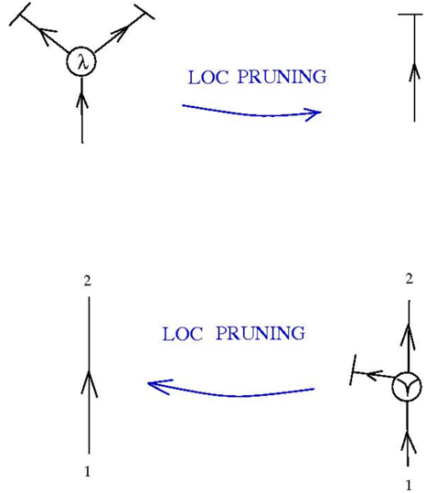
The image depicts a diagram illustrating the concept of "LOC Pruning". It shows a transformation from a complex node structure to a simplified linear structure through a pruning process. The diagram consists of two sets of transformations, each with an initial node, a pruning arrow, and a resulting linear structure.
### Components/Axes
The diagram contains the following components:
* **Nodes:** Represented by circles with internal symbols (λ and a Y-shaped symbol).
* **Arrows:** Indicate input and output connections to the nodes.
* **Pruning Arrows:** Blue arrows labeled "LOC PRUNING" showing the transformation direction.
* **Linear Structures:** Vertical lines with numerical labels (1 and 2) indicating input/output points.
* **Labels:** "λ" inside the first node, and "LOC PRUNING" labeling the pruning arrows.
* **Numerical Labels:** "1" and "2" on the vertical lines.
### Detailed Analysis or Content Details
**Transformation 1 (Top):**
* **Initial Node:** A circle containing the symbol "λ". Three arrows point towards the circle, and three arrows point away from it.
* **Pruning Arrow:** A blue arrow labeled "LOC PRUNING" points from the initial node to the right.
* **Resulting Structure:** A single vertical line with an arrow pointing upwards.
**Transformation 2 (Bottom):**
* **Initial Node:** A circle containing a Y-shaped symbol. Two arrows point towards the circle, and two arrows point away from it.
* **Pruning Arrow:** A blue arrow labeled "LOC PRUNING" points from the initial node to the left.
* **Resulting Structure:** A single vertical line with an arrow pointing upwards. The line is labeled with "1" at the bottom and "2" at the top.
### Key Observations
* The "LOC Pruning" process appears to simplify a complex node with multiple connections into a single linear pathway.
* The pruning arrows indicate a directional transformation.
* The numerical labels (1 and 2) on the bottom structure suggest a sequential flow or ordering.
* The initial nodes have different internal symbols (λ and Y-shaped), suggesting different types of initial structures.
### Interpretation
The diagram illustrates a simplification process called "LOC Pruning". The initial nodes represent complex operations or decision points with multiple inputs and outputs. The "LOC Pruning" process reduces this complexity to a single linear pathway, potentially representing a streamlined or optimized operation. The numerical labels on the bottom structure suggest a sequential order of operations or data flow. The different symbols within the initial nodes suggest that the pruning process can be applied to different types of complex structures.
The diagram doesn't provide quantitative data, but rather a conceptual illustration of a transformation. It suggests that LOC Pruning is a method for reducing complexity and streamlining processes. The use of arrows and labels clearly communicates the direction and nature of the transformation. The diagram is a visual representation of an algorithmic or computational process.