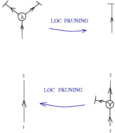
## Diagram: LOC PRUNING Process Flow
### Overview
The image contains two interconnected diagrams illustrating a "LOC PRUNING" process. Both diagrams use directional arrows and labeled nodes to represent transformations. The diagrams are connected by a blue arrow labeled "LOC PRUNING," indicating a sequential or iterative process.
---
### Components/Axes
1. **Top Diagram**:
- **Central Node**: Labeled `λ` (lambda), with three outgoing arrows:
- Two arrows branching left and right (horizontal divergence).
- One arrow pointing downward (vertical continuation).
- **Arrows**: Black lines with arrowheads indicating direction.
- **Text**: "LOC PRUNING" in blue, positioned below the diagram with an arrow pointing to the right.
2. **Bottom Diagram**:
- **Vertical Line**: Labeled `1` (bottom) and `2` (top), suggesting hierarchical levels or steps.
- **Horizontal Arrow**: Points leftward from the vertical line, labeled "LOC PRUNING."
- **Final Node**: A `Y`-shaped node with two outgoing arrows (left and right divergence).
- **Arrows**: Black lines with arrowheads.
---
### Detailed Analysis
- **Top Diagram**:
- The `λ` node acts as a source or decision point, splitting into two paths (left/right) while maintaining a downward path.
- The "LOC PRUNING" label and arrow suggest a transformation or filtering step applied to this structure.
- **Bottom Diagram**:
- The vertical line (`1` to `2`) may represent a prioritized or ordered sequence.
- The leftward arrow from the vertical line indicates a reversal or reorientation of flow.
- The `Y`-shaped node introduces a new divergence, possibly representing optimized or simplified pathways after pruning.
---
### Key Observations
1. **Process Flow**:
- The top diagram’s `λ` node undergoes "LOC PRUNING," resulting in the bottom diagram’s restructured `Y`-shaped node.
- The vertical labels (`1`, `2`) imply a two-stage process or prioritization.
2. **Structural Changes**:
- The top diagram’s horizontal divergence is replaced by a vertical hierarchy in the bottom diagram.
- The final `Y`-shaped node retains divergence but in a different orientation, suggesting selective path retention.
3. **No Numerical Data**:
- The diagrams lack quantitative values, focusing instead on symbolic representation of flow and structure.
---
### Interpretation
The diagrams depict a **LOC PRUNING** process that simplifies or optimizes a branching structure. The top diagram represents an initial complex configuration (`λ` node with multiple paths), while the bottom diagram shows a streamlined outcome after pruning. Key insights:
- **Pruning Mechanism**: The process removes redundant or low-priority paths (e.g., the top diagram’s horizontal divergence is replaced by a vertical hierarchy).
- **Hierarchical Optimization**: The vertical labels (`1`, `2`) may indicate prioritization, with higher-level paths (`2`) retained after pruning.
- **Flow Reorientation**: The leftward arrow in the bottom diagram suggests a reversal of direction, possibly to align with downstream requirements.
This process could model computational optimizations (e.g., reducing decision trees), resource allocation, or workflow simplification in technical systems.