# Technical Document Extraction: Distributed Training Failure Recovery Diagram
## 1. Document Overview
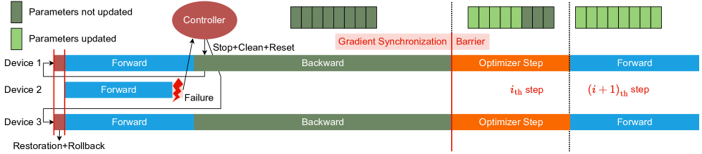
This image is a technical timing diagram illustrating a fault-tolerance mechanism in a distributed machine learning environment across multiple devices. It details the interaction between a central controller and three computing devices during a failure event, recovery, and subsequent synchronization.
---
## 2. Component Isolation
### A. Legend (Top Left)
* **Location:** [x: 0-200, y: 0-150]
* **Dark Green Square:** "Parameters not updated"
* **Light Green Square:** "Parameters updated"
### B. Header / Global State (Top Center/Right)
* **Controller:** A red oval representing the central management unit.
* **Parameter State Bars:** Horizontal segmented bars showing the status of model parameters.
* **Initial State:** All segments are Dark Green (Not updated).
* **Post-Barrier State:** Most segments are Light Green, some remain Dark Green.
* **Final State:** All segments are Light Green (Updated).
* **Text Labels:**
* "Gradient Synchronization Barrier" (Red text, split by a vertical red line).
### C. Main Timeline (Center)
* **Y-Axis (Devices):** Device 1, Device 2, Device 3.
* **X-Axis (Process Flow):**
* **Forward Pass (Blue):** Active on all devices initially.
* **Backward Pass (Muted Green):** Active on Device 1 and Device 3.
* **Optimizer Step (Orange):** Active on Device 1 and Device 3 after the barrier.
* **Step Indicators (Red Text):**
* $i_{th}$ step
* $(i + 1)_{th}$ step
### D. Footer / Control Signals (Bottom Left)
* **Text:** "Restoration+Rollback" with arrows pointing to the start of the timeline.
---
## 3. Process Flow and Logic Analysis
### Phase 1: Failure and Detection
1. **Execution:** Devices 1, 2, and 3 begin the **Forward** pass (Blue bars).
2. **Event:** A red lightning bolt icon labeled **"Failure"** occurs on **Device 2** during its Forward pass.
3. **Communication:** An arrow points from the failure point on Device 2 to the **Controller**.
### Phase 2: Controller Intervention
1. **Command:** The Controller issues a **"Stop+Clean+Reset"** signal (indicated by downward arrows) to the other active devices.
2. **Rollback:** A vertical red shaded region at the start of the timeline is labeled **"Restoration+Rollback"**. Arrows indicate that the system resets to the beginning of the current step.
### Phase 3: Resilient Execution (The $i_{th}$ step)
1. **Forward/Backward:** Device 1 and Device 3 proceed through the **Forward** (Blue) and **Backward** (Muted Green) passes. Note that Device 2 remains inactive/absent during this phase.
2. **Synchronization:** A vertical red line marks the **"Gradient Synchronization Barrier"**.
3. **Optimization:** After the barrier, Device 1 and Device 3 perform the **Optimizer Step** (Orange).
4. **Parameter Update:** Above this section, the parameter bar changes from all Dark Green to mostly Light Green, indicating the model is being updated despite the missing device.
### Phase 4: Transition to $(i + 1)_{th}$ step
1. **Boundary:** A vertical dotted black line separates the $i_{th}$ step from the $(i + 1)_{th}$ step.
2. **Completion:** The parameter bar at the top right is now entirely Light Green ("Parameters updated").
3. **Next Iteration:** Device 1 and Device 3 begin the next **Forward** pass.
---
## 4. Summary of Textual Data
| Category | Exact Transcription |
| :--- | :--- |
| **Legend** | Parameters not updated, Parameters updated |
| **Components** | Controller, Device 1, Device 2, Device 3 |
| **Actions/States** | Forward, Backward, Optimizer Step, Failure, Restoration+Rollback, Stop+Clean+Reset |
| **Synchronization** | Gradient Synchronization Barrier |
| **Iteration Markers** | $i_{th}$ step, $(i + 1)_{th}$ step |
---
## 5. Technical Observations
* **Fault Tolerance:** The diagram depicts a "subset" update strategy. When Device 2 fails, the Controller resets the remaining devices (1 and 3), which then complete the $i_{th}$ iteration and update the parameters without waiting for Device 2 to recover.
* **Color Coding Consistency:**
* **Blue** always represents the Forward pass.
* **Muted Green** always represents the Backward pass.
* **Orange** always represents the Optimizer Step.
* **Red** is reserved for control signals, failures, and synchronization barriers.