## System Architecture Diagram: Automated Test Case Generation Pipeline
### Overview
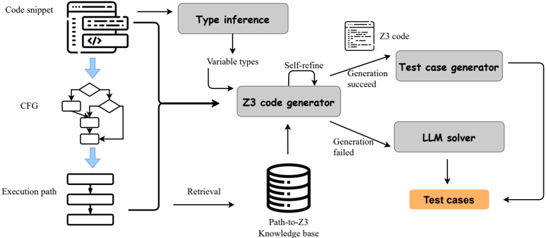
This image is a technical flowchart illustrating a multi-stage pipeline for automatically generating test cases from code snippets. The system combines static analysis (Control Flow Graph), symbolic execution (Z3 solver), and large language models (LLM) in a hybrid approach. The process includes a feedback loop for refinement and a knowledge base for retrieval.
### Components/Axes
The diagram is organized into interconnected functional blocks with directional arrows indicating data and control flow.
**Primary Components (Boxes):**
| Component | Description | Location |
| :--- | :--- | :--- |
| **Code snippet** | Represented by a document icon with code lines. | Top-left |
| **CFG** | Stands for Control Flow Graph, depicted as a flowchart with decision diamonds and process rectangles. | Below Code snippet |
| **Execution path** | A linear sequence of rectangular blocks. | Below CFG |
| **Type inference** | A gray rectangular box. | Top-center |
| **Z3 code generator** | A large gray rectangular box, the central processing unit. | Center |
| **Test case generator** | A gray rectangular box. | Top-right |
| **LLM solver** | A gray rectangular box. | Bottom-right |
| **Path-to-Z3 Knowledge base** | Represented by a database cylinder icon. | Bottom-center |
| **Test cases** | An orange rectangular box, the final output. | Bottom-right, below LLM solver |
**Labels and Annotations on Arrows/Connections:**
* `Variable types` (Arrow from Type inference to Z3 code generator)
* `Self-refine` (Circular arrow on the Z3 code generator)
* `Z3 code` (Arrow from Z3 code generator to Test case generator)
* `Generation succeed` (Arrow from Z3 code generator to Test case generator)
* `Generation failed` (Arrow from Z3 code generator to LLM solver)
* `Retrieval` (Arrow from Knowledge base to Z3 code generator)
### Detailed Analysis
The process flow can be segmented into three main phases:
**1. Input Processing & Analysis (Left Side):**
* A **Code snippet** is the starting input.
* It is analyzed in two parallel paths:
* **Path A (Static Analysis):** The code is parsed to create a **CFG** (Control Flow Graph), which is then used to determine an **Execution path**.
* **Path B (Type Analysis):** The code undergoes **Type inference** to determine **Variable types**.
* Both the **Execution path** and the **Variable types** are fed as inputs into the central **Z3 code generator**.
**2. Core Generation & Decision Logic (Center & Right):**
* The **Z3 code generator** is the core component. It has a **Self-refine** loop, indicating an iterative improvement process.
* It also performs **Retrieval** from the **Path-to-Z3 Knowledge base**, suggesting it uses stored examples or patterns to aid generation.
* The generator has two possible outcomes:
* **Success Path:** If generation succeeds, it outputs **Z3 code** to the **Test case generator**.
* **Failure Path:** If generation fails, the task is passed to the **LLM solver**.
**3. Output Generation (Right Side):**
* The **Test case generator** (receiving successful Z3 code) and the **LLM solver** (handling failures) both produce the final output: **Test cases**.
* The **Test cases** box is highlighted in orange, distinguishing it as the primary deliverable of the entire pipeline.
### Key Observations
* **Hybrid Architecture:** The system uses a primary, formal method (Z3 symbolic execution) with a fallback, probabilistic method (LLM). This suggests a design that prioritizes correctness (via Z3) but maintains robustness (via LLM).
* **Knowledge-Augmented Generation:** The inclusion of a **Path-to-Z3 Knowledge base** with a retrieval mechanism indicates the system learns from past examples to improve the Z3 code generation, moving beyond a purely rule-based approach.
* **Iterative Refinement:** The **Self-refine** loop on the Z3 generator implies it doesn't produce a single output but iteratively improves its generated code, likely checking against constraints or test oracles.
* **Spatial Layout:** The flow is generally left-to-right (input to output) and top-to-bottom (analysis to final output). The central placement of the **Z3 code generator** emphasizes its role as the primary decision and processing hub.
### Interpretation
This diagram represents a sophisticated software engineering automation tool, likely for **symbolic execution-based test generation**. The pipeline addresses a key challenge: automatically creating inputs (test cases) that explore specific paths in a program.
* **What it demonstrates:** The system first tries to formally model the program's behavior and constraints using Z3 (a theorem prover) to generate precise test cases. The **CFG** and **Execution path** define *what* to test, while **Type inference** and the **Knowledge base** help define *how* to model it for Z3.
* **Relationships:** The LLM solver acts as a "safety net," ensuring the pipeline always produces an output, even when the formal method fails. This is a pragmatic design choice, acknowledging that symbolic execution can be brittle or computationally expensive for complex code.
* **Notable Implication:** The **Path-to-Z3 Knowledge base** is critical. It transforms the system from a static tool into a potentially learning one, where successful generations for similar code patterns can be reused, improving efficiency and success rates over time. The entire architecture balances the precision of formal methods with the flexibility of machine learning.