\n
## Diagram: System Process Flow
### Overview
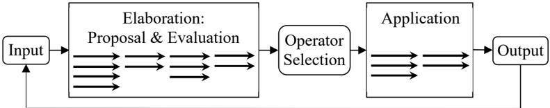
The image depicts a system process flow diagram illustrating a sequence of operations from input to output, involving elaboration, operator selection, and application stages. The diagram uses boxes to represent processes and arrows to indicate the flow of information or control.
### Components/Axes
The diagram consists of the following components:
* **Input:** Represented by a rounded rectangle on the left side.
* **Elaboration: Proposal & Evaluation:** A large rectangle containing multiple parallel arrows, indicating iterative processes. The text "Elaboration: Proposal & Evaluation" is centered within this rectangle.
* **Operator Selection:** A smaller rectangle positioned between "Elaboration" and "Application". The text "Operator Selection" is centered within this rectangle.
* **Application:** A rectangle containing multiple parallel arrows, similar to "Elaboration". The text "Application" is centered within this rectangle.
* **Output:** Represented by a rounded rectangle on the right side.
* **Arrows:** Arrows connect the components, indicating the direction of the process flow. There is a feedback loop from "Output" to "Input".
### Detailed Analysis or Content Details
The diagram shows a process that begins with an "Input". This input is then fed into the "Elaboration: Proposal & Evaluation" stage. Within this stage, there are approximately 6 parallel arrows, suggesting multiple simultaneous or iterative processes. The output of "Elaboration" is then passed to "Operator Selection". From "Operator Selection", the process moves to the "Application" stage, which also contains approximately 6 parallel arrows, indicating multiple simultaneous or iterative processes. Finally, the "Application" stage produces an "Output". A feedback loop is present, connecting the "Output" back to the "Input", suggesting a cyclical or iterative system.
### Key Observations
The diagram emphasizes iterative processes within both the "Elaboration" and "Application" stages. The feedback loop indicates a system that learns or adapts based on its output. The "Operator Selection" stage acts as a crucial intermediary between the elaboration and application phases.
### Interpretation
This diagram likely represents a problem-solving or decision-making process. The "Elaboration" stage represents the generation and evaluation of potential solutions ("Proposal & Evaluation"). "Operator Selection" could represent the choice of the best solution or method. The "Application" stage then implements the chosen solution, and the "Output" represents the result. The feedback loop suggests that the system continuously refines its approach based on the results it achieves. The parallel arrows within "Elaboration" and "Application" suggest that multiple options are considered or processed concurrently, potentially leading to a more robust or efficient solution. This could be a model for a control system, an AI learning loop, or a complex engineering design process.