## Diagram: Workflow for LLM-based Hardware Design
### Overview
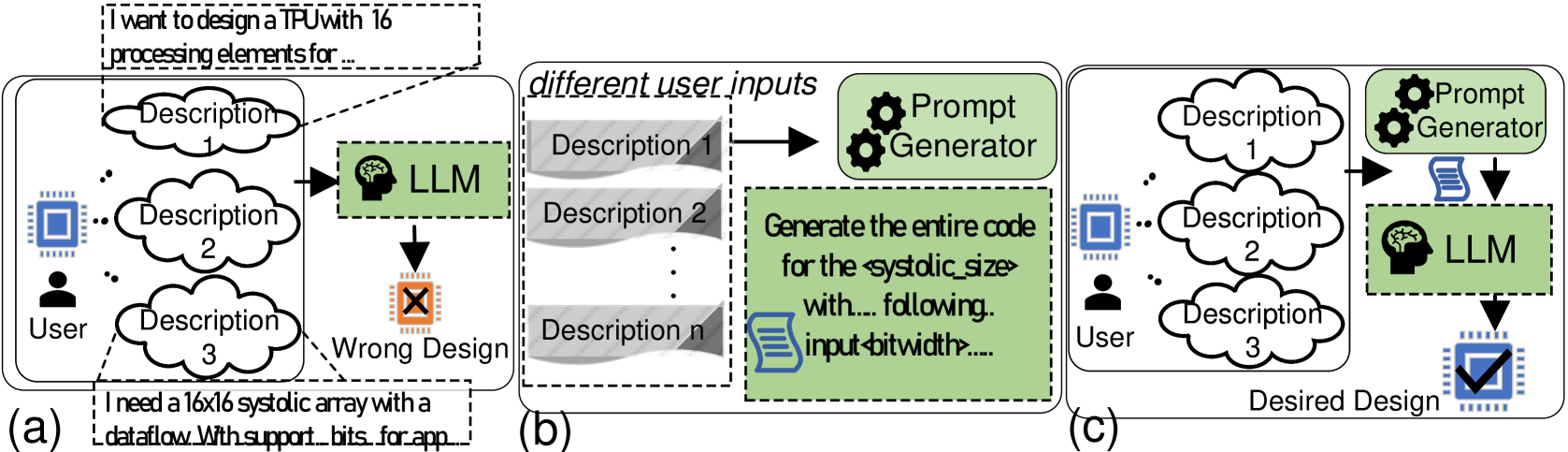
This diagram illustrates a conceptual workflow for using Large Language Models (LLMs) to design hardware, specifically focusing on the transition from an ineffective, direct-prompting approach to a structured, prompt-engineered approach. The diagram is divided into three distinct sections: (a) the naive/failed approach, (b) the prompt generation process, and (c) the optimized/successful approach.
### Components/Axes
The diagram is organized horizontally from left to right, representing a process flow.
* **Section (a) - The Naive Approach:**
* **Top Dashed Box:** Contains the text: "I want to design a TPU with 16 processing elements for ..."
* **Left:** A "User" icon connected to three cloud-shaped bubbles labeled "Description 1", "Description 2", and "Description 3".
* **Right:** A green box labeled "LLM" (with a brain icon).
* **Bottom:** A red "X" over a chip icon labeled "Wrong Design".
* **Bottom Dashed Box:** Contains the text: "I need a 16x16 systolic array with a dataflow with support bits for app ..."
* **Section (b) - The Prompt Generation Process:**
* **Header:** "different user inputs"
* **Left:** A stack of gray boxes labeled "Description 1", "Description 2", "...", "Description n".
* **Top Right:** A green box with gear icons labeled "Prompt Generator".
* **Bottom Right:** A large green box containing a document icon and the text: "Generate the entire code for the <systolic_size> with... following.. input <bitwidth>....".
* **Section (c) - The Optimized Approach:**
* **Left:** A "User" icon connected to three cloud-shaped bubbles labeled "Description 1", "Description 2", and "Description 3".
* **Right:** A "Prompt Generator" (green box with gears) feeding into an "LLM" (green box with brain icon).
* **Bottom:** A blue checkmark over a chip icon labeled "Desired Design".
### Detailed Analysis
* **Section (a) Analysis:** This section depicts a direct interaction between a user and an LLM. The user provides vague, natural language descriptions (e.g., "I want to design a TPU..."). The LLM attempts to process this, but the outcome is marked with a red "X," indicating a "Wrong Design." This suggests that direct, unstructured prompting is insufficient for complex hardware generation.
* **Section (b) Analysis:** This section isolates the "Prompt Generator" component. It takes various "different user inputs" (Descriptions 1 through n) and processes them through a "Prompt Generator." The output is a structured template (the large green box) that forces the inclusion of specific technical parameters, specifically `<systolic_size>` and `<input_bitwidth>`.
* **Section (c) Analysis:** This section combines the elements from (a) and (b). The user provides descriptions, which are passed through the "Prompt Generator" to create a structured prompt. This structured prompt is then fed into the "LLM." The result is a blue checkmark over a chip icon, labeled "Desired Design," indicating a successful outcome.
### Key Observations
* **The "Prompt Generator" as a Bridge:** The diagram explicitly positions the "Prompt Generator" as the critical intermediary that transforms ambiguous user intent into actionable, structured technical specifications.
* **Parameterization:** The transition from (a) to (c) highlights the shift from natural language ("16 processing elements") to parameterized variables (`<systolic_size>`, `<input_bitwidth>`).
* **Failure vs. Success:** The visual contrast between the red "X" in (a) and the blue checkmark in (c) serves as a clear indicator of the efficacy of the proposed methodology.
### Interpretation
This diagram demonstrates the necessity of **Prompt Engineering** in the context of automated hardware design. It suggests that LLMs, while powerful, lack the inherent capability to derive precise hardware specifications (like systolic array dimensions or bit-widths) from vague, high-level user descriptions.
The "Prompt Generator" acts as a semantic translator. By forcing the user's input into a rigid template—specifically requesting variables like `<systolic_size>` and `<input_bitwidth>`—the system ensures the LLM receives the necessary constraints to generate functional, correct hardware code. This implies that for domain-specific tasks like hardware design, the "human-in-the-loop" or "automated-pre-processing" step is essential to bridge the gap between human intent and machine-executable code.