\n
## Diagram: TPU Design Process with LLM
### Overview
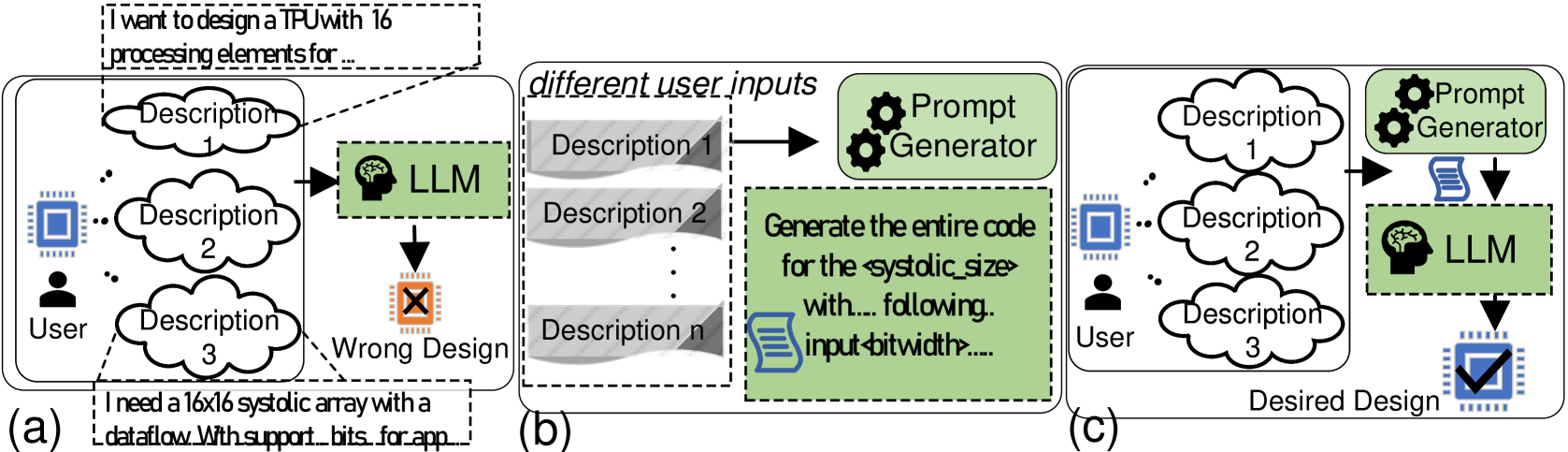
The image presents a diagram illustrating three different approaches (a, b, and c) to designing a TPU (Tensor Processing Unit) using a Large Language Model (LLM). The diagram focuses on how user descriptions are processed and translated into a design, highlighting the impact of prompt generation on the final outcome.
### Components/Axes
The diagram consists of three main sections labeled (a), (b), and (c), each representing a different design process. Common elements include:
* **User:** Represented by a silhouette icon.
* **Description 1, Description 2, Description 3... Description n:** Cloud-shaped elements representing user input descriptions.
* **LLM:** A stylized brain icon representing the Large Language Model.
* **Prompt Generator:** A gear icon representing a component that generates prompts.
* **Arrows:** Indicate the flow of information.
* **"Wrong Design"**: A red "X" symbol indicating a failed design outcome.
* **"Desired Design"**: A blue checkmark symbol indicating a successful design outcome.
* **Text Boxes:** Contain example user inputs.
### Detailed Analysis or Content Details
**Section (a): Direct Input**
* A user provides multiple descriptions (Description 1, 2, 3) directly to the LLM.
* The LLM attempts to generate a design.
* The outcome is labeled "Wrong Design" with a red "X".
* User input example 1: "I want to design a TPU with 16 processing elements for..."
* User input example 2: "I need a 16x16 systolic array with a dataflow With support bits for app..."
**Section (b): Prompt Generation - Incorrect**
* The user provides multiple descriptions (Description 1, 2, n) to a Prompt Generator.
* The Prompt Generator creates a prompt and sends it to the LLM.
* The LLM generates code based on the prompt.
* The outcome is not explicitly labeled as wrong, but the overall flow suggests an undesirable result.
* Prompt example: "Generate the entire code for the systolic size with... following input bitwidth..."
**Section (c): Prompt Generation - Correct**
* The user provides multiple descriptions (Description 1, 2, 3) to a Prompt Generator.
* The Prompt Generator creates a prompt and sends it to the LLM.
* The LLM generates a design.
* The outcome is labeled "Desired Design" with a blue checkmark.
### Key Observations
* The diagram highlights the importance of prompt generation when using an LLM for design tasks.
* Direct input from the user to the LLM (section a) results in a "Wrong Design".
* Using a Prompt Generator improves the outcome, as demonstrated by the "Desired Design" in section (c).
* Section (b) suggests that even with a Prompt Generator, the quality of the prompt is crucial for achieving the desired result.
### Interpretation
The diagram illustrates a workflow for utilizing LLMs in hardware design, specifically for TPUs. It demonstrates that simply feeding user descriptions directly to an LLM is insufficient for generating a correct design. The introduction of a Prompt Generator acts as an intermediary, refining the user's intent into a format that the LLM can effectively process. The success of the Prompt Generator is critical; a poorly generated prompt (as potentially implied in section b) can still lead to suboptimal results. The diagram suggests that effective prompt engineering is a key factor in leveraging LLMs for complex design tasks. The use of visual cues like the red "X" and blue checkmark reinforces the idea that the prompt generation step is a binary success/failure point. The diagram doesn't provide quantitative data, but rather a qualitative comparison of different approaches. It's a conceptual illustration of a design process, emphasizing the role of prompt engineering in achieving desired outcomes.