\n
## Diagram: LLM-Based Hardware Design Generation Process Comparison
### Overview
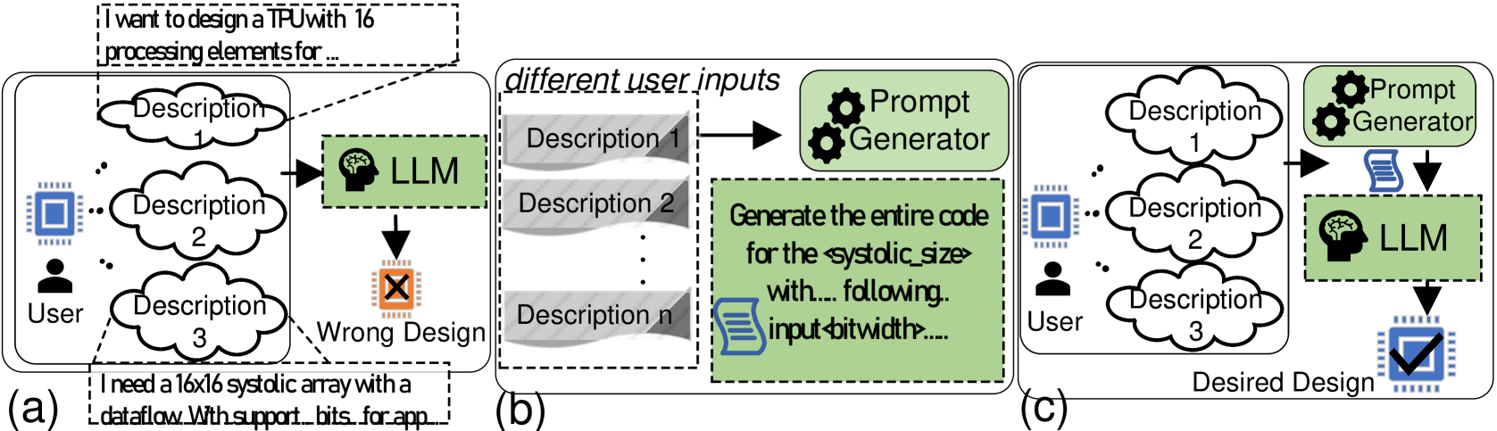
The image is a three-part diagram (labeled a, b, c) illustrating different workflows for generating hardware designs (specifically a TPU/systolic array) using a Large Language Model (LLM). It contrasts a flawed direct approach with an improved method that incorporates a "Prompt Generator" to refine user inputs before LLM processing.
### Components/Axes
The diagram is divided into three distinct panels arranged horizontally:
* **Panel (a):** Leftmost panel, labeled "(a)". Depicts a direct, flawed process.
* **Panel (b):** Center panel, labeled "(b)". Depicts an intermediate step of prompt generation.
* **Panel (c):** Rightmost panel, labeled "(c)". Depicts the improved, desired process.
**Key Components & Labels:**
* **User:** Represented by a person icon. Present in panels (a) and (c).
* **Chip/Design Icon:** A blue square chip icon. Present in all panels, representing the hardware design goal.
* **LLM:** Represented by a green box containing a brain icon and the text "LLM". Present in all panels.
* **Prompt Generator:** Represented by a green box containing two gear icons and the text "Prompt Generator". Present in panels (b) and (c).
* **Descriptions:** Represented by cloud-shaped bubbles labeled "Description 1", "Description 2", "Description 3", etc.
* **Design Output Icons:**
* **Wrong Design:** An orange chip icon with a black 'X' inside, in panel (a).
* **Desired Design:** A blue chip icon with a black checkmark inside, in panel (c).
* **Text Bubbles/Callouts:**
* Top-left of (a): "I want to design a TPU with 16 processing elements for..."
* Bottom-left of (a): "I need a 16x16 systolic array with a dataflow With support... bits for app..."
* Center of (b): A green box with the text: "Generate the entire code for the `<systolic_size>` with... following. input `<bitwidth>`...."
* **Flow Arrows:** Black arrows indicate the direction of data/process flow between components.
### Detailed Analysis
**Panel (a) - Direct LLM Input (Flawed Process):**
1. **Spatial Layout:** The User icon is on the far left. Three description clouds ("Description 1", "2", "3") are stacked vertically to its right. The LLM box is to the right of the descriptions. The "Wrong Design" icon is below the LLM.
2. **Flow:** User -> Multiple Descriptions -> LLM -> Wrong Design.
3. **Textual Content:** Two example user prompts are shown in dashed-line callouts pointing to the description clouds:
* Top callout: "I want to design a TPU with 16 processing elements for..."
* Bottom callout: "I need a 16x16 systolic array with a dataflow With support... bits for app..."
* The ellipses (...) indicate the text is truncated.
**Panel (b) - Prompt Generation (Intermediate Step):**
1. **Spatial Layout:** A dashed box labeled "different user inputs" contains a stack of gray, wavy-edged boxes labeled "Description 1", "Description 2", ..., "Description n". An arrow points from this stack to the "Prompt Generator" box. Below the Prompt Generator is a large green text box.
2. **Flow:** Multiple User Inputs -> Prompt Generator -> [Generated Prompt].
3. **Textual Content:** The green text box contains a template for a generated prompt:
* "Generate the entire code for the `<systolic_size>` with... following. input `<bitwidth>`...."
* The angle brackets `< >` denote placeholder variables.
**Panel (c) - Improved Process with Prompt Generator:**
1. **Spatial Layout:** Similar to (a), with the User icon on the left and three description clouds. However, the flow is different. An arrow points from the descriptions to the "Prompt Generator" box (top right). An arrow from the Prompt Generator points down to a document icon, which then points to the LLM box. The "Desired Design" icon is below the LLM.
2. **Flow:** User -> Descriptions -> Prompt Generator -> [Refined Prompt as Document] -> LLM -> Desired Design.
3. **Key Difference:** The Prompt Generator acts as an intermediary, processing the raw user descriptions before they reach the LLM.
### Key Observations
1. **Process Evolution:** The diagram shows a clear progression from a naive, error-prone method (a) to a more robust method (c) by introducing a dedicated prompt engineering step (b).
2. **Role of the Prompt Generator:** Its function is to take multiple, potentially vague or incomplete user descriptions ("Description 1...n") and synthesize them into a single, structured, and detailed prompt (as shown in the green box in panel b) suitable for the LLM.
3. **Visual Coding of Success/Failure:** The outcome is color-coded and symbolized: an orange chip with an 'X' for failure ("Wrong Design") versus a blue chip with a checkmark for success ("Desired Design").
4. **Input Complexity:** The user's initial requests (shown in panel a) are specific but appear to be natural language fragments. The system in (c) is designed to handle such inputs more effectively.
### Interpretation
This diagram argues that directly using natural language user descriptions to prompt an LLM for complex hardware design tasks is unreliable and leads to incorrect outputs ("Wrong Design"). The core problem is the gap between informal human requirements and the precise specifications needed by an LLM to generate correct hardware description language (HDL) code.
The proposed solution is a **Prompt Generator** module. This component acts as a translator and refiner. It takes the user's high-level, possibly fragmented or ambiguous descriptions and transforms them into a formal, detailed, and structured prompt. The example prompt template ("Generate the entire code for the `<systolic_size>`...") shows this output includes explicit parameters and clear instructions.
The improved workflow in panel (c) demonstrates that inserting this automated prompt engineering step between the user and the LLM significantly increases the likelihood of achieving the "Desired Design." It highlights the importance of **prompt quality** in LLM-based code generation for specialized domains like hardware design, suggesting that the LLM's capability is unlocked not by the model alone, but by the quality of its input instructions. The diagram is likely from a research paper or technical proposal advocating for such a two-stage (or multi-stage) generation framework.