## Diagram: Technical Workflow for Systolic Array Design with LLM Integration
### Overview
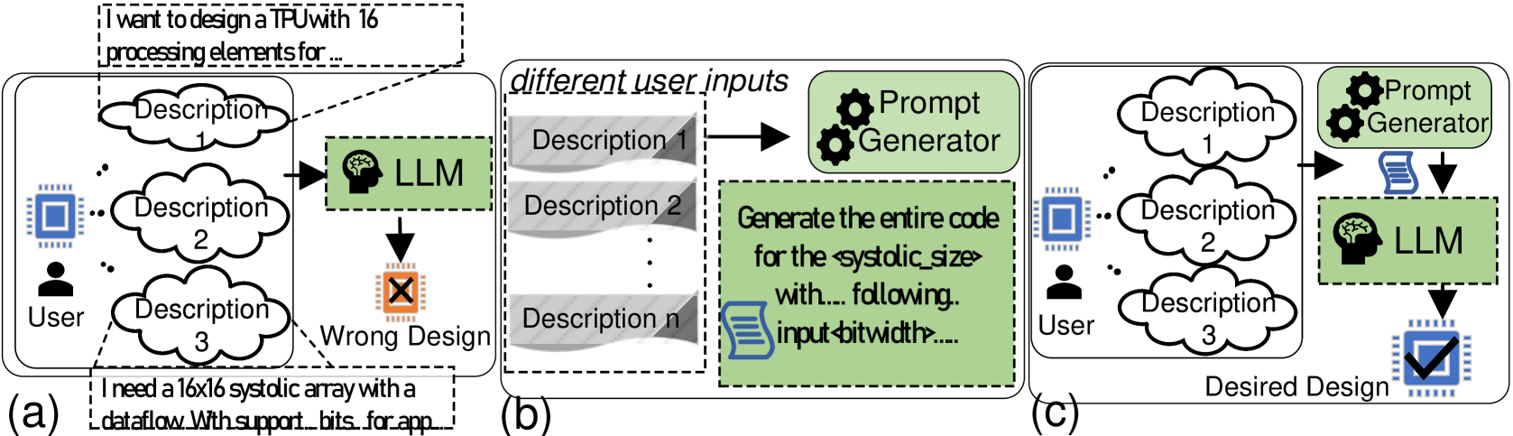
The diagram illustrates a three-stage technical workflow for designing a systolic array using a Large Language Model (LLM) and prompt engineering. It contrasts incorrect and correct design outcomes based on user input processing. Three labeled sections (a, b, c) depict progressive stages of the process.
### Components/Axes
1. **User Input Section**
- Three cloud-shaped nodes labeled "Description 1," "Description 2," and "Description 3" represent user requirements.
- Arrows indicate flow from user to LLM (brain icon) and prompt generator (gear icon).
2. **Processing Components**
- **LLM (Large Language Model)**: Green box with brain icon, positioned centrally in all sections.
- **Prompt Generator**: Gear icon, responsible for code generation.
- **Output Nodes**:
- "Wrong Design" (red X) in section (a).
- "Desired Design" (blue checkmark) in section (c).
3. **Textual Descriptions**
- **Section (a)**: User input specifies "16x16 systolic array with dataflow with support bits for app..."
- **Section (b)**: Prompt generator task: "Generate the entire code for the systolic_size with... input_bitwidth..."
- **Section (c)**: Final output labeled "Desired Design" with checkmark.
### Detailed Analysis
- **Section (a)**:
User provides three descriptions to the LLM, which outputs a "Wrong Design" (red X). The LLM lacks explicit guidance on systolic array parameters.
- **Section (b)**:
User inputs are processed by a **Prompt Generator**, which refines requirements into structured code specifications (e.g., systolic array dimensions, bitwidth).
- **Section (c)**:
The prompt generator feeds refined specifications to the LLM, resulting in a "Desired Design" (blue checkmark).
### Key Observations
1. **Flow Direction**:
- Left-to-right progression from raw user input to final design.
- Sections (a) and (c) share identical user inputs but differ in LLM interaction.
2. **Critical Path**:
- The prompt generator acts as a bridge between ambiguous user requirements and precise LLM output.
3. **Symbol Consistency**:
- Brain icon (LLM) and gear icon (prompt generator) are spatially anchored near their respective processing stages.
### Interpretation
The diagram emphasizes the necessity of **prompt engineering** to transform vague user requirements into actionable technical specifications. Without the prompt generator (section a), the LLM produces an incorrect design. With it (sections b and c), the LLM generates the desired systolic array code. This highlights the LLM's dependency on structured input for accurate technical output, aligning with principles of human-AI collaboration in engineering workflows.