## Diagram: Environment and Automaton Representation
### Overview
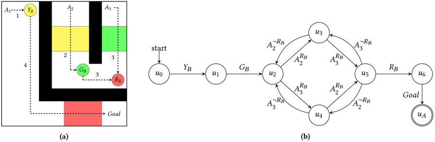
The image consists of two distinct parts labeled (a) and (b).
* **Part (a)** displays a grid-based environment (a maze) containing obstacles (black bars), colored regions (yellow, green, red), and labeled navigation paths.
* **Part (b)** displays a state transition diagram (a finite automaton) with nodes labeled $u_0$ through $u_6$ and $u_A$, connected by directed edges with logical transition labels.
This figure likely represents a formal methods or robotics planning problem, where the maze (a) is the physical environment and the automaton (b) is the task specification or controller logic.
### Components/Axes
#### Part (a): Environment
* **Layout:** A square grid containing black rectangular obstacles.
* **Colored Regions:**
* **Yellow:** Located in the top-middle section.
* **Green:** Located in the top-right section.
* **Red:** Located in the bottom-middle section.
* **Labeled Points/Markers:**
* $Y_B$: A yellow circle in the top-left.
* $G_B$: A green circle in the middle-left.
* $R_B$: A red circle in the middle-right.
* **Paths/Arrows:**
* Dashed arrows indicate movement paths labeled $A_1, A_2, A_3$.
* Numerical labels "1", "2", "3", and "4" are placed near specific path segments.
* "Goal" text is located at the bottom-right of the red region.
#### Part (b): Automaton
* **Nodes:** Circles labeled $u_0, u_1, u_2, u_3, u_4, u_5, u_6$.
* **Accepting State:** $u_A$ (represented by a double-circled node).
* **Transitions:** Directed edges between nodes, labeled with logical conditions (e.g., $A_2^{R_B}$, $G_B$, $R_B$).
---
### Detailed Analysis
#### Part (a): Environment Navigation
* **Pathing:**
* $A_1$ (top-left) leads to $Y_B$.
* $A_2$ (top-middle) leads to $G_B$.
* $A_3$ (top-right) leads to $R_B$.
* A path labeled "4" originates from $Y_B$ and travels downward to the bottom red region.
* A path labeled "3" originates from $G_B$ and travels rightward toward $R_B$.
* **Spatial Grounding:** The environment is partitioned by black walls. The agent must navigate around these walls to reach the "Goal" located in the bottom red zone.
#### Part (b): Automaton Transitions
The automaton defines the valid sequence of states.
* **Start:** The process begins at $u_0$.
* **Sequence:**
* $u_0 \xrightarrow{Y_B} u_1$
* $u_1 \xrightarrow{G_B} u_2$
* **Branching Logic (from $u_2$):**
* $u_2 \xrightarrow{A_2^{R_B}} u_3$
* $u_2 \xrightarrow{A_3^{\neg R_B}} u_4$
* **Feedback Loops:**
* $u_3 \xrightarrow{A_2^{\neg R_B}} u_2$
* $u_4 \xrightarrow{A_3^{\neg R_B}} u_2$
* **Progression to Goal:**
* $u_3 \xrightarrow{A_3^{R_B}} u_5$
* $u_4 \xrightarrow{A_2^{R_B}} u_5$
* $u_5 \xrightarrow{R_B} u_6$
* $u_6 \xrightarrow{Goal} u_A$
* **Reverse/Correction Transitions:**
* $u_5 \xrightarrow{A_3^{\neg R_B}} u_3$
* $u_5 \xrightarrow{A_2^{\neg R_B}} u_4$
---
### Key Observations
* **Logical Notation:** The superscripts (e.g., $R_B, \neg R_B$) in the automaton represent boolean conditions. $R_B$ likely denotes "Is the agent in the Red region?" and $\neg R_B$ denotes "Is the agent NOT in the Red region?".
* **State Dependency:** The automaton requires the agent to visit specific locations ($Y_B, G_B$) before proceeding to the branching logic involving $A_2$ and $A_3$.
* **Goal Reachability:** The final state $u_A$ is only reachable after passing through $u_6$, which requires the condition $R_B$ to be met (likely meaning the agent must be in the red region).
### Interpretation
This diagram illustrates a **Formal Verification or Symbolic Planning problem**.
1. **The Environment (a)** acts as the physical constraints for an agent. The agent must navigate the grid, and the colored regions serve as "landmarks" or "regions of interest" that trigger specific logical propositions.
2. **The Automaton (b)** acts as the **Task Specification**. It dictates the order of operations. For example, the agent *must* visit $Y_B$ and $G_B$ first (transitions $u_0 \to u_1 \to u_2$).
3. **The Branching:** Once at $u_2$, the agent's path depends on the environment state. If the agent performs action $A_2$ while in the Red region ($R_B$), it moves to $u_3$. If it performs $A_3$ while *not* in the Red region ($\neg R_B$), it moves to $u_4$.
4. **The Goal:** The system is designed to ensure the agent reaches the "Goal" state ($u_A$) only after satisfying the complex sequence of conditions defined by the automaton. This is a standard representation used in **Linear Temporal Logic (LTL)** synthesis, where the goal is to synthesize a controller that satisfies the automaton's requirements while navigating the physical maze.