\n
## Diagram: System Flow with Operators
### Overview
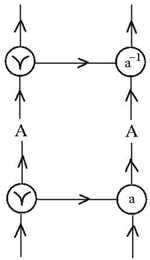
The image depicts a diagram representing a system flow with two main loops. Each loop contains a circular node labeled with a mathematical operator and a symbol within the circle. Arrows indicate the direction of flow within the loops. Labels "A" and "Y" are placed alongside the loops, indicating input or output.
### Components/Axes
The diagram consists of the following components:
* **Circular Nodes:** Two circular nodes, one labeled "a" and the other labeled "a⁻¹" (a inverse).
* **Symbols within Circles:** Each circular node contains a symbol resembling a "Y" shape.
* **Arrows:** Arrows indicating the direction of flow between the nodes and external inputs/outputs.
* **Labels:** "A" and "Y" labels positioned alongside the loops.
* **Input/Output Lines:** Vertical lines representing input or output to the system.
### Detailed Analysis or Content Details
The diagram shows two interconnected loops.
* **Loop 1 (Bottom):**
* Starts with an input line.
* Flows into a circular node containing the symbol "Y" and labeled "a".
* Flows out of the "a" node and continues to another input line.
* The label "A" is positioned alongside the flow between the input/output lines and the "a" node.
* **Loop 2 (Top):**
* Starts with an input line.
* Flows into a circular node containing the symbol "Y" and labeled "a⁻¹".
* Flows out of the "a⁻¹" node and continues to another input line.
* The label "A" is positioned alongside the flow between the input/output lines and the "a⁻¹" node.
* **Interconnection:**
* A horizontal arrow connects the output of the "Y" node in the bottom loop to the input of the "a⁻¹" node in the top loop.
* A horizontal arrow connects the output of the "Y" node in the top loop to the input of the "a" node in the bottom loop.
### Key Observations
The diagram represents a system where an input is processed by an operator "a" in one loop and its inverse "a⁻¹" in the other. The "Y" symbol within the circles suggests a branching or splitting operation. The loops are interconnected, indicating a feedback or iterative process.
### Interpretation
This diagram likely represents a mathematical or signal processing system. The "a" and "a⁻¹" operators suggest a forward and inverse transformation. The "Y" symbol could represent a bifurcation or splitting of a signal. The interconnected loops suggest a system where the output of one transformation is fed back into the other, potentially for iterative refinement or error correction. The "A" label could represent an input signal or a control parameter, while "Y" could represent an output or a branching point. Without further context, it's difficult to determine the specific function of this system, but it appears to be a closed-loop system involving transformations and feedback. The diagram is abstract and does not provide specific numerical data or values. It is a conceptual representation of a system's structure and flow.