\n
## Diagram: KV Cache Workflow with Prefill, Decode, Verify, and Rollback
### Overview
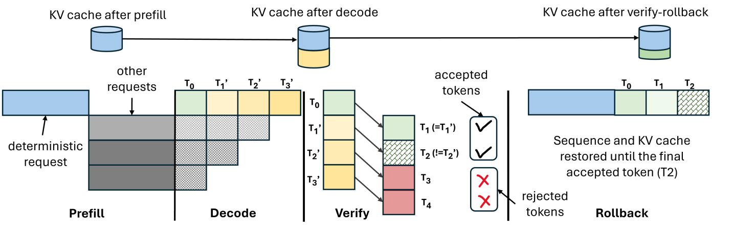
This diagram illustrates a workflow involving a KV (Key-Value) cache across four stages: Prefill, Decode, Verify, and Rollback. It depicts how a deterministic request progresses through these stages, interacting with the KV cache and undergoing token acceptance or rejection. The diagram highlights the state of the KV cache at each stage and the handling of accepted and rejected tokens.
### Components/Axes
The diagram is segmented into four main sections, each representing a stage in the workflow:
1. **Prefill:** Shows the initial deterministic request and the KV cache state.
2. **Decode:** Illustrates the decoding process and the KV cache update.
3. **Verify:** Depicts the verification stage, token acceptance/rejection, and the KV cache state.
4. **Rollback:** Shows the rollback process and the final KV cache state.
There are also labels indicating:
* "KV cache after prefill"
* "KV cache after decode"
* "KV cache after verify-rollback"
* "other requests"
* "accepted tokens"
* "rejected tokens"
* Time steps: T₀, T₁', T₂', T₃', T₁, T₂, T₃, T₄
### Detailed Analysis or Content Details
**Prefill:**
* A blue block represents the "deterministic request" with an arrow indicating its entry point.
* Above the block is a cylinder labeled "KV cache after prefill", indicating an initial state.
**Decode:**
* The deterministic request transitions into a series of four blocks representing time steps: T₀, T₁', T₂', T₃'. These blocks are stacked vertically.
* Above the blocks is a cylinder labeled "KV cache after decode", indicating the cache state after decoding.
* "other requests" are shown as an arrow pointing towards the decode stage.
**Verify:**
* Four blocks are shown, representing time steps: T₀, T₁', T₂', T₃', T₄.
* T₁ (=T₁') is marked with a green checkmark, indicating acceptance.
* T₂ (=T₂) is marked with a green checkmark, indicating acceptance.
* T₃ is marked with a red "X", indicating rejection.
* T₄ is marked with a red "X", indicating rejection.
* The blocks representing accepted tokens are colored light green, while rejected tokens are colored red.
* Above the blocks is a cylinder labeled "KV cache after verify-rollback", indicating the cache state after verification and potential rollback.
**Rollback:**
* A series of three blocks representing time steps: T₀, T₁, T₂. These blocks are colored light green.
* Text states: "Sequence and KV cache restored until the final accepted token (T2)".
### Key Observations
* The workflow is sequential, progressing from Prefill to Decode, Verify, and potentially Rollback.
* The KV cache is updated at each stage, reflecting the accepted tokens.
* Rejected tokens trigger a rollback mechanism, restoring the sequence and KV cache to the state before the rejected token.
* The time steps are denoted with primes (T₁', T₂', T₃') during the decode stage, and without primes (T₁, T₂) after verification.
* The diagram clearly illustrates the concept of speculative execution (Decode) followed by verification and potential correction (Verify/Rollback).
### Interpretation
The diagram demonstrates a mechanism for handling speculative execution in a system utilizing a KV cache. The "deterministic request" initiates the process, and the "Decode" stage speculatively processes tokens. The "Verify" stage then checks the validity of these tokens. If tokens are rejected, the "Rollback" stage restores the system to a consistent state, ensuring that only accepted tokens are committed to the KV cache. This approach allows for efficient processing while maintaining data integrity. The use of a KV cache suggests an optimization strategy to reduce latency by storing frequently accessed data. The diagram highlights the importance of verification and rollback in handling potential errors during speculative execution. The time step notation (primes vs. no primes) indicates a distinction between the speculative and committed states of the tokens.