## Diagram: p-Computer Architecture and 1-bit RNG Implementation
### Overview
The image presents two interconnected technical diagrams:
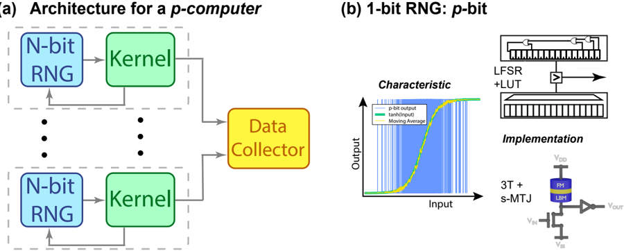
1. **(a) Architecture for a p-computer**: A system with N-bit RNGs feeding into kernels, which aggregate data into a central collector.
2. **(b) 1-bit RNG: p-bit**: A characteristic graph and hardware implementation of a pseudo-random number generator (RNG) producing binary outputs.
---
### Components/Axes
#### (a) p-Computer Architecture
- **Components**:
- **N-bit RNG**: Blue boxes labeled "N-bit RNG" (top and bottom).
- **Kernel**: Green boxes labeled "Kernel" (center).
- **Data Collector**: Orange box labeled "Data Collector" (right).
- **Flow**:
- Arrows connect N-bit RNGs → Kernels → Data Collector.
- Dashed lines indicate feedback loops from Kernels to N-bit RNGs.
#### (b) 1-bit RNG: p-bit
- **Graph**:
- **X-axis**: "Input" (horizontal).
- **Y-axis**: "Output" (vertical).
- **Lines**:
- **Blue**: "p-bit output" (step function).
- **Green**: "tanh(input)" (smooth curve).
- **Yellow**: "Moving Average" (smoothed step function).
- **Legend**: Located on the right, with color-coded labels.
- **Implementation**:
- Circuit diagram with labeled components:
- **LFSR** (Linear Feedback Shift Register).
- **LUT** (Look-Up Table).
- **3T + s-MTJ** (3-transistor + spintronic magnetoresistive junction).
- **FM** (Ferromagnetic) and **LBM** (Local Bit Manipulation).
- Voltage labels: **VDD**, **VIN**, **VSS**, **VOUT**.
---
### Detailed Analysis
#### (a) p-Computer Architecture
- **Structure**:
- Two N-bit RNGs (top and bottom) generate random data.
- Kernels process inputs from RNGs and feed results to the Data Collector.
- Feedback loops suggest iterative refinement of RNG outputs.
#### (b) 1-bit RNG: p-bit
- **Graph Trends**:
- **p-bit output**: Binary step function (blue line) with abrupt transitions between 0 and 1.
- **tanh(input)**: Smooth sigmoid curve (green line), mapping input to [-1, 1].
- **Moving Average**: Yellow line smooths the p-bit steps, reducing noise.
- **Implementation**:
- **LFSR**: Generates pseudo-random bits.
- **LUT**: Maps LFSR outputs to p-bit values.
- **3T + s-MTJ**: Hardware implementation for energy-efficient bit manipulation.
---
### Key Observations
1. **p-bit Output**: Binary steps (blue line) indicate discrete 0/1 states, typical of RNGs.
2. **tanh(input)**: Smooth transition suggests input normalization for analog processing.
3. **Moving Average**: Yellow line demonstrates noise reduction in binary data.
4. **Hardware Components**:
- **LFSR** and **LUT** enable deterministic pseudo-randomness.
- **3T + s-MTJ** implies low-power, high-density spintronic logic.
---
### Interpretation
- **p-Computer Architecture**:
- The system uses multiple N-bit RNGs to generate diverse random data, processed by kernels for aggregation. Feedback loops may optimize RNG performance or adapt to data patterns.
- **1-bit RNG**:
- The p-bit output (blue line) is a binary signal, while the tanh(input) (green) provides a continuous analog representation. The moving average (yellow) filters noise, critical for reliable data collection.
- **Hardware Implementation**:
- The 3T + s-MTJ circuit highlights a focus on energy-efficient, spintronic-based computing, aligning with emerging non-volatile memory technologies.
- **Significance**:
- The architecture bridges probabilistic computing (p-computer) with hardware implementations, emphasizing scalability (N-bit RNGs) and noise resilience (moving average).