## Diagram: Diagram of a Transformation
### Overview
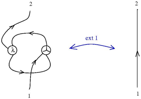
The image shows a diagram illustrating a transformation of a complex loop structure into a simple vertical line. The diagram consists of two main parts connected by a blue, curved, double-headed arrow labeled "ext 1". The left side depicts a loop with internal nodes, while the right side shows a straight line. Arrows indicate the direction of flow or transformation.
### Components/Axes
* **Left Side:** A complex loop structure with two nodes.
* Node 1: Contains the Greek letter lambda (λ).
* Node 2: Contains a three-pronged symbol.
* The loop has arrows indicating direction.
* The bottom of the loop is labeled "1".
* The top of the loop is labeled "2".
* **Right Side:** A straight vertical line with an arrow indicating direction.
* The bottom of the line is labeled "1".
* The top of the line is labeled "2".
* **Connector:** A blue, curved, double-headed arrow labeled "ext 1" connects the left and right sides, indicating a transformation.
### Detailed Analysis or ### Content Details
* **Left Side Loop:**
* The loop starts at the bottom, labeled "1".
* The loop splits into two paths.
* One path goes to the node containing lambda (λ).
* The other path goes to the node containing the three-pronged symbol.
* The paths rejoin and exit at the top, labeled "2".
* Arrows along the paths indicate the direction of flow.
* **Right Side Line:**
* A straight vertical line starts at the bottom, labeled "1".
* An arrow indicates the direction of flow upwards.
* The line ends at the top, labeled "2".
* **Transformation:**
* The blue, curved, double-headed arrow labeled "ext 1" indicates a transformation from the complex loop structure on the left to the simple vertical line on the right.
### Key Observations
* The diagram illustrates a simplification or transformation of a complex structure into a simpler one.
* The labels "1" and "2" likely represent input and output points, respectively.
* The nodes within the loop on the left likely represent specific operations or components.
* The "ext 1" label suggests an external operation or transformation.
### Interpretation
The diagram likely represents a mathematical or physical process where a complex system or interaction (represented by the loop structure) is simplified or transformed into a more basic form (represented by the straight line). The "ext 1" label suggests that this transformation is achieved through an external operation or interaction. The nodes containing lambda (λ) and the three-pronged symbol likely represent specific parameters or components within the system that are affected by the transformation. The arrows indicate the direction of flow or transformation, suggesting a process that moves from input "1" to output "2".