## Diagram: Cyclic System with Linear Extension
### Overview
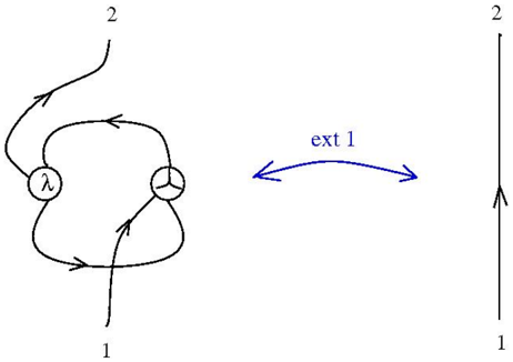
The image depicts a technical diagram with two distinct components:
1. A **looped structure** on the left containing two labeled nodes (`λ` and `μ`) connected by directional arrows forming a closed cycle.
2. A **vertical line** on the right with directional arrows at the top and bottom labeled `2` and `1`, respectively.
A bidirectional arrow labeled `ext 1` connects the looped structure to the vertical line, suggesting an interaction or extension between the two systems.
### Components/Axes
- **Looped Structure**:
- Nodes:
- Left node labeled `λ` (Greek letter lambda).
- Right node labeled `μ` (Greek letter mu).
- Arrows:
- Four directional arrows forming a closed loop between `λ` and `μ`.
- Arrows are unlabeled but imply cyclical flow.
- **Vertical Line**:
- A single vertical line with two directional arrows:
- Top arrow labeled `2` (pointing upward).
- Bottom arrow labeled `1` (pointing downward).
- **Connection**:
- A bidirectional arrow labeled `ext 1` links the looped structure to the vertical line.
### Detailed Analysis
- **Looped Structure**:
- The cycle between `λ` and `μ` suggests a feedback or iterative process.
- No numerical values or additional labels are present on the arrows or nodes.
- **Vertical Line**:
- The labels `2` (top) and `1` (bottom) may indicate hierarchical levels, states, or positions.
- The directional arrows imply a unidirectional flow (upward and downward).
- **Connection (`ext 1`)**:
- The bidirectional arrow `ext 1` implies a two-way interaction or extension between the looped system and the linear system.
### Key Observations
1. The looped structure (`λ` ↔ `μ`) represents a self-contained cyclic process.
2. The vertical line (`2` ↔ `1`) represents a linear, hierarchical, or sequential system.
3. The `ext 1` connection suggests the looped system is extended or integrated with the linear system.
### Interpretation
This diagram likely models a system where:
- **Cyclic processes** (e.g., feedback loops, iterative workflows) interact with **linear hierarchies** (e.g., decision trees, state transitions).
- The `ext 1` label indicates a critical interface or dependency between the two subsystems.
- The absence of numerical data or units suggests the diagram is conceptual, focusing on structural relationships rather than quantitative metrics.
**Notable Patterns**:
- The looped structure’s symmetry implies balanced interactions between `λ` and `μ`.
- The vertical line’s asymmetry (top `2`, bottom `1`) may denote a priority or directional preference.
- The bidirectional `ext 1` arrow highlights a non-hierarchical, mutual relationship between the systems.
**Underlying Implications**:
- The diagram could represent a technical workflow, such as a software architecture where a cyclical module (`λ`/`μ`) extends a linear process (`ext 1`).
- Alternatively, it might model a biological or physical system with feedback loops and linear pathways.
- The lack of explicit data points or units leaves the interpretation open to domain-specific context.