## Diagram: AgentFlow and In-the-Flow Rollout
### Overview
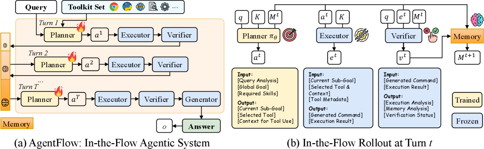
The image presents two diagrams illustrating the AgentFlow system and its in-the-flow rollout at a specific turn *t*. Diagram (a) shows the overall iterative process of the AgentFlow agentic system, while diagram (b) details the individual components and data flow within a single turn.
### Components/Axes
**Diagram (a): AgentFlow: In-the-Flow Agentic System**
* **Title:** (a) AgentFlow: In-the-Flow Agentic System
* **Input:** Query, Toolkit Set (with icons representing Google, Python, and other tools)
* **Turns:** The system operates in turns, labeled "Turn 1", "Turn 2", and "Turn T".
* **Components per Turn:** Each turn consists of a Planner, Executor, and Verifier. In the final turn, a Generator is added.
* **Memory:** A vertical orange bar labeled "Memory" runs along the left side, with brain icons indicating memory updates between turns.
* **Output:** The final output is labeled "Answer".
* **Nodes:** Planner, Executor, Verifier, Generator, Answer, Memory
* **Edges:** Arrows indicate the flow of information between components.
**Diagram (b): In-the-Flow Rollout at Turn *t***
* **Title:** (b) In-the-Flow Rollout at Turn *t*
* **Components:** Planner, Executor, Verifier, Memory
* **Inputs to Planner:** q (query), K (knowledge), Mt (memory at time t)
* **Output from Planner:** at (action at time t)
* **Input to Executor:** at (action at time t), K (knowledge)
* **Output from Executor:** et (execution at time t)
* **Input to Verifier:** q (query), et (execution at time t), Mt (memory at time t)
* **Output from Verifier:** vt (verification at time t)
* **Memory Update:** The Verifier's output and the current memory (Mt) are used to update the memory to Mt+1.
* **Input/Output Boxes:** Yellow boxes describe the inputs and outputs for the Planner, Executor, and Verifier.
* **Training Status:** "Trained" and "Frozen" labels indicate the training status of the system.
### Detailed Analysis or ### Content Details
**Diagram (a): AgentFlow: In-the-Flow Agentic System**
* **Turn 1:** Query flows into the Planner, which outputs a1 to the Executor. The Executor's output goes to the Verifier.
* **Turn 2:** The process repeats with Planner outputting a2.
* **Turn T:** The process repeats with Planner outputting aT. The Verifier's output goes to the Generator, which, along with input 'o', produces the final Answer.
* **Memory Updates:** After each turn, the Memory is updated, indicated by the brain icon.
**Diagram (b): In-the-Flow Rollout at Turn *t***
* **Planner:**
* Input: [Query Analysis], [Global Goal], [Required Skills]
* Output: [Current Sub-Goal], [Selected Tool], [Context for Tool Use]
* **Executor:**
* Input: [Current Sub-Goal], [Selected Tool & Context], [Tool Metadata]
* Output: [Generated Command], [Execution Result]
* **Verifier:**
* Input: [Generated Command], [Execution Result]
* Output: [Execution Analysis], [Memory Analysis], [Verification Status]
* **Memory:** Updated from Mt to Mt+1 based on the Verifier's output.
### Key Observations
* **Iterative Process:** AgentFlow is an iterative process, refining its actions over multiple turns.
* **Modular Design:** Each turn consists of distinct modules (Planner, Executor, Verifier) with specific roles.
* **Memory Integration:** Memory plays a crucial role in maintaining context and improving performance across turns.
* **Input/Output Specialization:** Each component (Planner, Executor, Verifier) has clearly defined inputs and outputs, facilitating modularity and reusability.
### Interpretation
The diagrams illustrate a sophisticated agentic system designed for complex tasks. The AgentFlow system uses an iterative approach, refining its actions over multiple turns. The Planner generates actions based on the query, knowledge, and memory. The Executor executes these actions, and the Verifier evaluates the results. The Memory component stores and updates information, allowing the system to learn and improve over time. The "In-the-Flow Rollout" diagram provides a detailed view of the data flow and processing within a single turn, highlighting the inputs and outputs of each component. The system is designed to be modular and flexible, allowing for easy integration of new tools and capabilities. The "Trained" and "Frozen" labels suggest that the system can be trained and then deployed in a fixed configuration.