## Diagram: AgentFlow System Architecture
### Overview
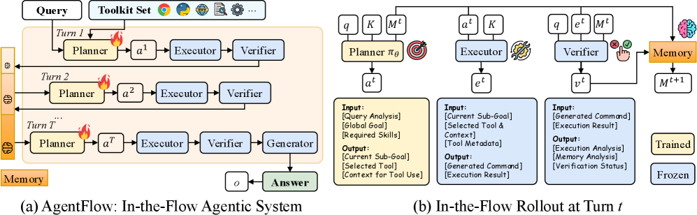
The image displays a two-part technical diagram illustrating the architecture of "AgentFlow," an agentic system designed for iterative problem-solving using tools. Part (a) shows the high-level, multi-turn system flow, while part (b) details the internal processing components and data flow for a single turn (`t`).
### Components/Axes
The diagram is divided into two labeled sections:
* **(a) AgentFlow: In-the-Flow Agentic System** (Left panel)
* **(b) In-the-Flow Rollout at Turn `t`** (Right panel)
**Part (a) Components:**
* **Input:** `Query`
* **Toolkit Set:** Represented by icons for a web browser, a globe, a document, a calculator, and a settings gear, followed by "..." indicating more tools.
* **Core Process:** A sequence of `Turn 1`, `Turn 2`, ... `Turn T...`. Each turn contains:
* `Planner` (yellow box with a flame icon)
* `Executor` (light blue box)
* `Verifier` (light blue box)
* **Flow:** Arrows show the sequence: `Query` -> `Planner` -> `Executor` -> `Verifier`. The output of one turn's `Verifier` feeds into the next turn's `Planner`.
* **Final Stage:** After the last turn, the flow goes to a `Generator` (light blue box), which outputs an `Answer` (green box). An arrow from `Generator` also points to a circle labeled `o`.
* **Memory:** A vertical orange bar on the far left labeled `Memory` connects to each turn's `Planner`.
**Part (b) Components:**
This panel breaks down the operations within a single turn `t`, showing three parallel processing blocks and a memory update.
* **Planner πθ (Trained):**
* **Input:** `q`, `K`, `M^t`
* **Output:** `a^t`
* **Input Description Box:** "Input: [Query Analysis], [Global Goal], [Required Skills]. Output: [Current Sub-Goal], [Selected Tool], [Context for Tool Use]."
* **Executor (Frozen):**
* **Input:** `a^t`, `K`
* **Output:** `e^t`
* **Input Description Box:** "Input: [Current Sub-Goal], [Selected Tool & Context], [Tool Metadata]. Output: [Generated Command], [Execution Result]."
* **Verifier (Frozen):**
* **Input:** `q`, `e^t`, `M^t`
* **Output:** `v^t`
* **Input Description Box:** "Input: [Generated Command], [Execution Result]. Output: [Execution Analysis], [Memory Analysis], [Verification Status]."
* **Memory Update:**
* The `Verifier`'s output `v^t` and the `Executor`'s output `e^t` feed into a `Memory` block (orange).
* This produces an updated memory state `M^(t+1)`.
* **Legend:** A box in the bottom-right corner defines the color coding:
* **Trained:** Yellow background (used for `Planner πθ`).
* **Frozen:** Light blue background (used for `Executor` and `Verifier`).
### Detailed Analysis
**Part (a) - System Flow:**
1. A `Query` is received.
2. The system enters an iterative loop for up to `T` turns.
3. In each turn `i`:
* The `Planner` (accessing `Memory`) generates an action `a^i`.
* The `Executor` runs the action.
* The `Verifier` checks the result.
* The verified output is passed to the next turn's `Planner`.
4. After the final turn, a `Generator` synthesizes all turn outputs into a final `Answer`.
**Part (b) - Single Turn (`t`) Rollout:**
* **Planner (`πθ`):** Takes the query (`q`), a knowledge base (`K`), and current memory (`M^t`). It outputs an action plan (`a^t`). This component is marked as **Trained**.
* **Executor:** Takes the action plan (`a^t`) and knowledge (`K`). It generates a command and executes it, producing an execution result (`e^t`). This component is **Frozen**.
* **Verifier:** Takes the original query (`q`), the execution result (`e^t`), and current memory (`M^t`). It produces a verification output (`v^t`). This component is **Frozen**.
* **Memory Update:** The outputs from the Executor (`e^t`) and Verifier (`v^t`) are used to update the system's memory from state `M^t` to `M^(t+1)`.
### Key Observations
1. **Iterative Refinement:** The core of AgentFlow is a multi-turn process where planning, execution, and verification are repeated, allowing for complex, multi-step problem-solving.
2. **Component Specialization:** The architecture clearly separates roles: Planning (learned/trained), Execution (fixed/frozen), and Verification (fixed/frozen).
3. **Central Role of Memory:** Memory (`M`) is a persistent state that is read from and written to in every turn, acting as the system's working context.
4. **Toolkit Abstraction:** The system is designed to work with a generic "Toolkit Set," implying it can be equipped with various APIs or tools.
5. **Flow Direction:** The data flow is strictly sequential within a turn (Planner -> Executor -> Verifier) and iterative across turns.
### Interpretation
This diagram describes a sophisticated AI agent framework designed for robust task completion. The "In-the-Flow" designation suggests the agent's reasoning and tool use are tightly integrated within a single operational pipeline.
* **The Peircean Investigation:** The process mirrors a scientific or investigative cycle. The **Planner** forms a hypothesis (action plan `a^t`) based on available data (`q`, `K`, `M^t`). The **Executor** conducts an experiment or gathers evidence (`e^t`). The **Verifier** analyzes the evidence against the original question (`q`) and existing knowledge (`M^t`) to assess its validity (`v^t`). This new evidence then updates the investigator's understanding (`M^(t+1)`), informing the next hypothesis. The final **Generator** synthesizes the findings into a conclusion (`Answer`).
* **Why It Matters:** This architecture addresses key challenges in autonomous AI: error correction (via the Verifier), long-horizon planning (via iterative turns), and state management (via Memory). By freezing the Executor and Verifier, the system may ensure reliable, predictable tool use and evaluation, while the trained Planner can adapt its strategies.
* **Notable Design Choice:** The separation of the "Trained" Planner from "Frozen" execution and verification modules suggests a design philosophy where core reasoning is learned, but the mechanisms for acting and checking are kept constant and reliable, potentially improving safety and predictability.