## Diagram: AgentFlow System Architecture and In-Flow Rollout Process
### Overview
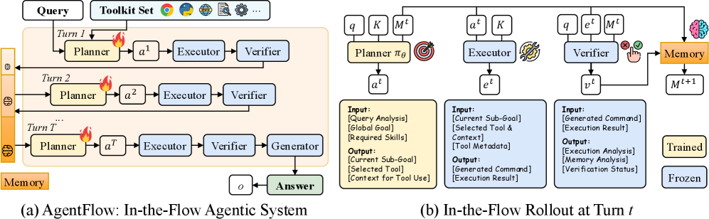
The image depicts a two-part technical diagram illustrating an agentic system's workflow and its in-flow rollout mechanics. Part (a) shows the system's general architecture across multiple turns, while part (b) details the component-level operations at a specific turn (t). The system integrates planning, execution, verification, and memory management components with explicit data flow between them.
### Components/Axes
**Part (a): AgentFlow Architecture**
- **Components**:
- Planner (labeled with fire icon)
- Executor
- Verifier
- Generator
- Memory (with "Trained" and "Frozen" states)
- **Flow**:
- Sequential progression from Query → Planner → Executor → Verifier → Generator → Answer
- Memory persists across turns (Turn 1 to Turn T)
- Toolkit Set icons (Chrome, Firefox, globe, etc.) appear at the top
**Part (b): In-Flow Rollout at Turn t**
- **Components**:
- Planner πθ (with target icon)
- Executor
- Verifier
- Memory (with brain icon)
- **Data Flow**:
- Inputs/Outputs for each component:
- Planner: [Query Analysis], [Global Goal], [Required Skills] → [Current Sub-Goal], [Selected Tool & Context], [Tool Metadata]
- Executor: [Generated Command] → [Execution Result]
- Verifier: [Execution Result] → [Execution Analysis], [Verification Status]
- Memory: [Memory Analysis] → [Memory Update]
### Detailed Analysis
**Part (a) Flow Mechanics**
1. **Turn Structure**:
- Each turn (1 to T) follows: Planner → Executor → Verifier → Generator
- Memory accumulates across turns (shown as stacked orange blocks)
2. **Component Roles**:
- Planner: Generates actions (a₁ to aᵀ) based on query and memory
- Executor: Executes actions with tool verification
- Verifier: Validates execution results
- Generator: Produces final answer (o) after T turns
**Part (b) Turn-Level Details**
1. **Planner πθ**:
- Inputs: Query analysis, global goal, required skills
- Outputs: Current sub-goal, selected tool/context, tool metadata
2. **Executor**:
- Input: Current sub-goal + context
- Output: Generated command + execution result
3. **Verifier**:
- Input: Execution result
- Output: Execution analysis + verification status (✓/✗)
4. **Memory**:
- Input: Verification status + execution analysis
- Output: Updated memory state (Mᵗ→Mᵗ⁺)
### Key Observations
1. **Cyclical Verification**:
- Verification occurs at every turn, with results feeding back into memory
2. **Memory Dynamics**:
- Memory contains both "Trained" (learned) and "Frozen" (static) components
3. **Tool Integration**:
- Tool selection and metadata are explicitly tracked through the workflow
4. **State Transitions**:
- Each turn updates memory (Mᵗ→Mᵗ⁺) based on verification outcomes
### Interpretation
This diagram illustrates a recursive agentic system where:
1. **Planning-Driven Execution**: The Planner (πθ) generates context-aware actions using memory-augmented query analysis
2. **Closed-Loop Verification**: Every execution result undergoes verification before memory updates, ensuring quality control
3. **Memory as Knowledge Base**: The system maintains both dynamic (Trained) and static (Frozen) knowledge, enabling context-aware tool selection
4. **Incremental Progress**: The T-turn structure suggests cumulative learning, with each verification result refining future planning
The architecture emphasizes reliability through continuous verification and memory-augmented planning, while the rollout mechanics show how individual turns contribute to long-term system improvement. The use of both trained and frozen memory components suggests a hybrid approach combining learned patterns with fixed domain knowledge.