## Diagram: Instruction Sequence and Data Flow Graph (DAG) Representation
### Overview
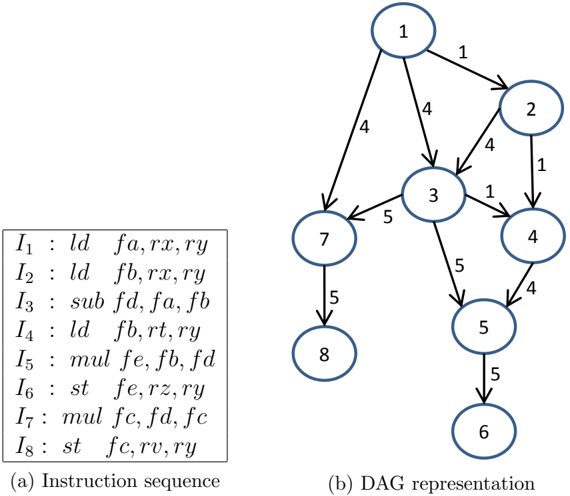
The image contains two components:
1. **(a) Instruction Sequence**: A table defining 8 instructions (I₁–I₈) with labels and operations.
2. **(b) DAG Representation**: A directed acyclic graph (DAG) with 8 nodes (1–8) connected by edges labeled with instruction numbers (1–8), illustrating data flow dependencies.
---
### Components/Axes
#### (a) Instruction Sequence Table
- **Structure**: 8 rows (I₁–I₈), each with:
- **Label**: Instruction identifier (e.g., `ld`, `sub`, `mul`, `st`).
- **Operations**: Comma-separated operands (e.g., `fa,rx,ry`).
- **Key Details**:
- `ld`: Load operations (e.g., `I₁: ld fa,rx,ry`).
- `sub`: Subtract (`I₃: sub fd,fa,fb`).
- `mul`: Multiply (`I₅: mul fe,fb,fd`).
- `st`: Store (`I₇: st fc,fd,fc`).
#### (b) DAG Representation
- **Nodes**: 8 nodes labeled 1–8.
- **Edges**: Directed arrows with instruction numbers (1–8) indicating transitions.
- Example: Node 1 → Node 2 (edge labeled `1`), Node 1 → Node 3 (edge labeled `4`).
- **Legend**: Edge numbers correspond to instruction numbers in the table (e.g., `1` = `I₁`, `4` = `I₄`).
---
### Detailed Analysis
#### (a) Instruction Sequence Table
| Instruction | Label | Operations |
|-------------|-------|---------------------|
| I₁ | ld | fa, rx, ry |
| I₂ | ld | fb, rx, ry |
| I₃ | sub | fd, fa, fb |
| I₄ | ld | fb, rt, ry |
| I₅ | mul | fe, fb, fd |
| I₆ | st | fe, rz, ry |
| I₇ | mul | fc, fd, fc |
| I₈ | st | fc, rv, ry |
#### (b) DAG Representation
- **Node Connections**:
- **Node 1**: Edges to 2 (1), 3 (4), 4 (4), 7 (5).
- **Node 2**: Edges to 3 (2), 5 (3), 6 (6).
- **Node 3**: Edges to 4 (1), 5 (7).
- **Node 4**: Edges to 5 (8).
- **Node 5**: Edges to 6 (5).
- **Node 6**: Edges to 7 (4).
- **Node 7**: Edges to 8 (7).
- **Node 8**: No outgoing edges.
---
### Key Observations
1. **Instruction Usage**:
- `I₁` (load) and `I₄` (load) are the most frequently used (4 edges each).
- `I₅` (mul) and `I₇` (mul) are used for intermediate computations.
- `I₈` (st) is the final store operation.
2. **Data Flow**:
- Nodes 1–5 represent computation stages, while nodes 6–8 handle storage.
- Node 5 (final computation) feeds into Node 6 (storage).
3. **Dependencies**:
- Node 1 initiates the flow, branching to multiple nodes via different instructions.
- Node 8 is a terminal node with no outgoing edges.
---
### Interpretation
- **Purpose**: The DAG visualizes the execution path of instructions, showing how data dependencies are resolved.
- **Critical Path**: The sequence `I₁ → I₄ → I₅ → I₇ → I₈` represents the primary computation and storage flow.
- **Anomalies**:
- Node 1 has multiple outgoing edges (4), indicating parallelism or branching logic.
- Node 3 and Node 4 both feed into Node 5, suggesting convergence of intermediate results.
- **Significance**: The diagram highlights the interplay between load/store operations (`ld`, `st`) and arithmetic operations (`sub`, `mul`), emphasizing the importance of instruction scheduling in data flow optimization.
---
**Note**: No numerical values or trends are present in the DAG; the focus is on structural relationships and instruction usage.