## Circuit Diagram: Learning Block and Programming Circuit
### Overview
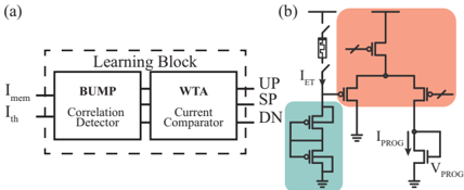
The image presents two circuit diagrams, labeled (a) and (b). Diagram (a) depicts a "Learning Block" composed of a "BUMP" (Correlation Detector) and a "WTA" (Current Comparator). Diagram (b) shows a programming circuit with transistors and a memristor.
### Components/Axes
**Diagram (a): Learning Block**
* **Title:** (a)
* **Overall Structure:** The Learning Block is enclosed in a dashed rectangle.
* **Input Currents:**
* I<sub>mem</sub> (input on the left)
* I<sub>th</sub> (input on the left)
* **Components:**
* **BUMP:** Labeled "BUMP" with the description "Correlation Detector" below it.
* **WTA:** Labeled "WTA" with the description "Current Comparator" below it.
* **Output Signals:**
* UP (output on the right)
* SP (output on the right)
* DN (output on the right)
**Diagram (b): Programming Circuit**
* **Title:** (b)
* **Key Components:**
* Memristor: Located at the top, connected to a switch.
* Transistors: Several transistors are arranged in a specific configuration.
* **Currents/Voltages:**
* I<sub>ET</sub> (current flowing from the memristor)
* I<sub>PROG</sub> (programming current)
* V<sub>PROG</sub> (programming voltage)
* **Highlighted Regions:**
* Top Region (Orange): Contains a set of transistors.
* Bottom-Left Region (Teal): Contains a stack of transistors connected to ground.
### Detailed Analysis or Content Details
**Diagram (a): Learning Block**
* The Learning Block takes two current inputs, I<sub>mem</sub> and I<sub>th</sub>.
* The BUMP block performs correlation detection.
* The WTA block performs current comparison.
* The Learning Block outputs three signals: UP, SP, and DN.
**Diagram (b): Programming Circuit**
* The circuit includes a memristor, which is a type of non-volatile memory.
* The current I<sub>ET</sub> flows from the memristor through a switch.
* The programming current I<sub>PROG</sub> is controlled by the programming voltage V<sub>PROG</sub>.
* The orange region contains a transistor configuration that likely serves as a current mirror or amplifier.
* The teal region contains a transistor configuration that likely serves as a current sink.
### Key Observations
* Diagram (a) represents a high-level functional block, while diagram (b) shows a detailed circuit implementation.
* The Learning Block likely uses the programming circuit to adjust its internal parameters or weights.
* The memristor in diagram (b) suggests that the learning process involves non-volatile storage of information.
### Interpretation
The image illustrates a system for implementing learning functionality using memristors. The Learning Block (a) performs the core learning operations, while the programming circuit (b) allows for adjusting the memristor's resistance, effectively storing the learned information. The BUMP and WTA blocks likely perform correlation detection and winner-take-all current comparison, respectively. The UP, SP, and DN signals could represent different states or outputs of the learning process. The programming circuit uses transistors to control the current flowing through the memristor, allowing for precise adjustment of its resistance. This setup suggests a neuromorphic computing approach, where memristors are used to emulate the behavior of synapses in the brain.