## BlockDiagram: Neuromorphic Learning System Architecture
### Overview
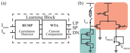
The image depicts a two-part technical system:
1. **Learning Block (a)**: A functional block diagram with labeled components and signal flow.
2. **Circuit Implementation (b)**: A physical circuit layout with labeled nodes, current sources, and voltage references.
### Components/Axes
#### Learning Block (a)
- **Inputs**:
- `I_mem` (memory input current)
- `I_th` (threshold input current)
- **Components**:
- **BUMP (Correlation Detector)**: Processes `I_mem` and `I_th` to generate correlation signals.
- **WTA (Current Comparator)**: Compares currents to produce winner-take-all outputs.
- **Outputs**:
- `UP` (up signal)
- `SP` (spike signal)
- `DN` (down signal)
#### Circuit Implementation (b)
- **Key Elements**:
- **Current Sources**:
- `I_ET` (error current)
- `I_PROG` (programming current)
- **Voltage Reference**: `V_PROG` (programming voltage)
- **Switches/Transistors**:
- Labeled as `UP`, `SP`, `DN` (matching Learning Block outputs).
- **Resistors/Inductors**:
- `L_ET` (error inductance)
- `R_PROG` (programming resistor)
- **Color Coding**:
- **Red Region**: Highlighted circuit section (likely error correction or programming path).
- **Blue Region**: Grounded or reference path.
### Detailed Analysis
#### Learning Block (a)
- **Signal Flow**:
- `I_mem` and `I_th` enter the Learning Block.
- BUMP computes correlation between inputs.
- WTA compares currents to select dominant signal (`UP`, `SP`, or `DN`).
- **Functional Roles**:
- BUMP: Likely implements spike-timing-dependent plasticity (STDP) or similar correlation logic.
- WTA: Ensures only the strongest signal propagates (common in neuromorphic architectures).
#### Circuit Implementation (b)
- **Current Paths**:
- `I_ET` flows through `L_ET` and `R_PROG`, suggesting an RL circuit for error dynamics.
- `I_PROG` is regulated by `V_PROG`, indicating programmable synaptic weight adjustment.
- **Component Relationships**:
- `UP`, `SP`, `DN` outputs from the Learning Block control switches in the circuit, linking abstract logic to physical implementation.
- `L_ET` and `R_PROG` form a feedback loop for error correction.
### Key Observations
1. **Modular Design**: The Learning Block abstracts computational logic, while the circuit provides a physical realization.
2. **Color-Coded Functionality**: Red and blue regions in (b) likely denote active (red) and passive/grounded (blue) paths.
3. **Bidirectional Control**: `I_PROG` and `V_PROG` suggest adjustable programming parameters for synaptic weight updates.
### Interpretation
This system appears to model a **neuromorphic learning architecture**, where:
- The Learning Block (a) represents abstract synaptic learning rules (e.g., STDP).
- The circuit (b) implements these rules using analog components (inductors, resistors) for energy-efficient computation.
- `I_ET` and `L_ET` imply error tracking for adaptive learning, while `I_PROG`/`V_PROG` enable synaptic weight programming.
The design bridges biological plausibility (WTA, correlation detection) with analog circuit principles, suggesting applications in low-power AI hardware or brain-inspired computing.