\n
## Diagram: Quantum Circuit Representation
### Overview
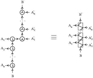
The image presents two equivalent representations of a quantum circuit. The left side shows a circuit diagram using standard quantum gate notation, while the right side depicts the same circuit using a different visual style, resembling a block diagram. An equality sign ("≡") connects the two representations, indicating their equivalence.
### Components/Axes
The diagram utilizes the following components:
* **Input/Output Lines:** Labeled 'B' at the bottom and 'B'' at the top.
* **Intermediate Lines:** Labeled 'A<sub>1</sub>', 'A<sub>2</sub>', ..., 'A<sub>n</sub>' at the bottom and 'A'<sub>1</sub>', 'A'<sub>2</sub>', ..., 'A'<sub>n</sub>' at the top.
* **Merging/Splitting Points:** Represented by 'Y' shaped junctions.
* **Lambda (λ) Symbols:** Representing a specific quantum operation or gate.
* **Rectangular Blocks:** In the right-hand side diagram, these represent the same operations as the lambda symbols and merging/splitting points on the left.
### Detailed Analysis or Content Details
**Left Side (Standard Quantum Circuit):**
The circuit starts with a single input line 'B'. This line splits into 'n' lines labeled 'A<sub>1</sub>' through 'A<sub>n</sub>' via lambda (λ) symbols. Each 'A<sub>i</sub>' line then converges with a corresponding 'A'<sub>i</sub>' line at another 'Y' junction. Finally, all 'A'<sub>i</sub>' lines merge into a single output line 'B''.
**Right Side (Block Diagram):**
The right side shows a series of rectangular blocks stacked vertically. The input 'B' enters the bottom block, and the output 'B'' exits the top block. Each block has two input/output lines: 'A<sub>i</sub>' and 'A'<sub>i</sub>'. The blocks are arranged in a sequence, with 'A<sub>1</sub>' and 'A'<sub>1</sub>' connected to the bottom block, 'A<sub>2</sub>' and 'A'<sub>2</sub>' to the middle block, and 'A<sub>n</sub>' and 'A'<sub>n</sub>' to the top block.
The arrangement suggests a parallel processing structure where each 'A<sub>i</sub>' line undergoes a transformation represented by the corresponding block, and the results are then combined to produce the output 'B''.
### Key Observations
* The two diagrams are visually distinct but represent the same quantum circuit.
* The lambda symbols and 'Y' junctions on the left correspond to the rectangular blocks on the right.
* The diagram illustrates a process of splitting an input into multiple parallel paths, processing each path independently, and then merging the results.
* The subscript notation (A<sub>i</sub>, A'<sub>i</sub>) indicates that the circuit operates on multiple qubits or quantum channels.
### Interpretation
This diagram likely represents a quantum operation that performs a controlled operation on multiple qubits. The splitting and merging of lines suggest a fan-out and fan-in structure, where the input qubit 'B' is applied to multiple qubits 'A<sub>i</sub>', and their results are combined to produce the output qubit 'B''. The lambda symbols and blocks likely represent quantum gates or unitary transformations that perform specific operations on the qubits.
The equivalence between the two representations highlights the flexibility in visualizing quantum circuits. The standard circuit notation is more common for describing individual gates and their connections, while the block diagram provides a more abstract view of the overall circuit structure. The diagram suggests a parallel processing scheme, which is a common technique in quantum computing to speed up computations. The use of subscripts indicates that the circuit operates on multiple qubits, which is essential for performing complex quantum algorithms. The diagram does not provide specific details about the quantum gates or transformations used, but it illustrates the general structure of a quantum circuit that performs a controlled operation on multiple qubits.