## Diagram: Process Transformation Flowchart
### Overview
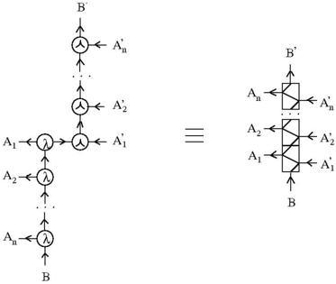
The image depicts two equivalent representations of a multi-stage transformation process. The left diagram shows a sequential flow of elements through transformation nodes, while the right diagram presents a consolidated block representation of the same process.
### Components/Axes
**Left Diagram:**
- **Nodes:**
- Input elements: `A₁, A₂, ..., Aₙ` (labeled sequentially from bottom to top)
- Transformation nodes: `λ` (lambda symbols) at each stage
- Output elements: `A'₁, A'₂, ..., A'ₙ` (transformed states of A₁ to Aₙ)
- Final output: `B'` (top node)
- **Arrows:**
- Vertical arrows connect `Aᵢ → λ → A'ᵢ` (transformation steps)
- Horizontal arrow connects `A'₁ → A'₂ → ... → A'ₙ → B'` (aggregation into final output)
**Right Diagram:**
- **Block Structure:**
- Input: `A₁, A₂, ..., Aₙ` (left side of block)
- Transformation: Diagonal arrows within a rectangular block labeled `B'`
- Output: `A'₁, A'₂, ..., A'ₙ` (right side of block)
- Final output: `B` (bottom node, equivalent to `B'` in left diagram)
**Shared Elements:**
- Lambda (`λ`) symbols denote transformation operations.
- Prime notation (`'`) indicates transformed states.
- Equivalence symbol (`≡`) links the two diagrams.
### Detailed Analysis
1. **Left Diagram Flow:**
- Each `Aᵢ` undergoes a transformation via `λ` to produce `A'ᵢ`.
- Transformed elements (`A'₁` to `A'ₙ`) are sequentially aggregated into `B'`.
- Vertical stacking implies hierarchical or sequential dependency.
2. **Right Diagram Structure:**
- The block represents a matrix-like transformation where inputs `Aᵢ` are mapped to outputs `A'ᵢ` via `B'`.
- Diagonal arrows suggest linear or direct mapping between input and output states.
- `B` at the bottom of the right diagram is equivalent to `B'` in the left diagram.
3. **Equivalence (`≡`):**
- The two diagrams represent the same process:
- Left: Stepwise transformation and aggregation.
- Right: Compact block representation of the same transformation.
### Key Observations
- **Consistency of Transformation:** The lambda (`λ`) symbols are identical in both diagrams, confirming the same operation is applied at each stage.
- **Prime Notation:** `A'ᵢ` and `B'` denote transformed states, while `B` (right diagram) is functionally equivalent to `B'`.
- **Dimensionality:** The left diagram emphasizes sequential processing, while the right diagram abstracts the process into a single block, suggesting a linear algebra or matrix-based interpretation.
### Interpretation
This diagram illustrates a **linear transformation pipeline** where:
1. Input elements (`Aᵢ`) are individually transformed via a function `λ` into intermediate states (`A'ᵢ`).
2. The transformed states are then combined (via aggregation or summation) into a final output (`B'` or `B`).
3. The equivalence (`≡`) implies that the stepwise process (left) and the block representation (right) are mathematically or computationally equivalent, likely representing a matrix operation or a linear system.
**Notable Patterns:**
- The use of primes (`'`) and lambda (`λ`) suggests a formal mathematical framework, possibly in linear algebra, signal processing, or control theory.
- The right diagram’s block structure hints at a matrix representation, where `B'` acts as a transformation matrix mapping `Aᵢ` to `A'ᵢ`.
**Underlying Assumptions:**
- The process is linear and reversible (implied by the equivalence symbol).
- The transformation `λ` is consistent across all `Aᵢ` elements.
- The final output (`B'`/`B`) depends on the cumulative effect of all transformed `A'ᵢ` elements.