## Flowchart Diagram: Logical/Computational Process
### Overview
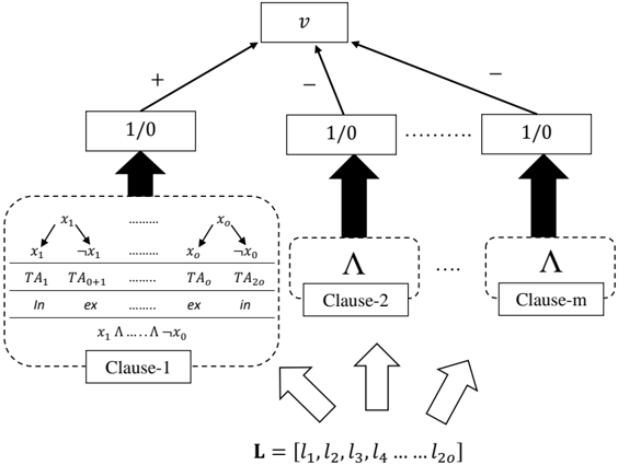
The diagram illustrates a hierarchical structure with a central node labeled "v" branching into three identical nodes labeled "1/0". Each "1/0" node connects to a clause (Clause-1, Clause-2, Clause-m), which then feed into a list L = [l₁, l₂, l₃, ..., l₂₀]. The leftmost section contains a detailed table with variables, transformations, and logical operators.
### Components/Axes
1. **Central Node**:
- Label: "v" (top-center)
- Connections:
- "+" arrow to left "1/0" node
- "-" arrow to middle "1/0" node
- "-" arrow to right "1/0" node
2. **"1/0" Nodes**:
- Three identical nodes arranged horizontally below "v"
- Each connects upward to "v" and downward to a clause
3. **Clauses**:
- Clause-1 (left): Contains a table with variables and transformations
- Clause-2 (middle): Simple label
- Clause-m (right): Simple label
4. **List L**:
- Positioned at bottom-center
- Contains elements l₁ to l₂₀
- Connected by arrows from all three clauses
5. **Left Table (Clause-1 Details)**:
- Variables: x₁, x₀, x₁', x₀'
- Transformations:
- "In" ↔ "ex"
- "TA₁" ↔ "TA₀₊₁"
- "TA₀" ↔ "TA₂₀"
- Logical operators: Λ (lambda), ¬ (negation)
### Detailed Analysis
- **Top Section**:
- "v" acts as a root node with dual polarity (+/-) influencing three identical "1/0" nodes
- Arrows suggest conditional branching based on "v"
- **Clause-1 Table**:
- Variables x₁ and x₀ appear in pairs with primed/non-primed states
- Transformations suggest state changes ("In"↔"ex", "TA" subscripts)
- Logical operators Λ and ¬ indicate boolean operations
- **Clause Connections**:
- Clause-1 contains detailed variable logic
- Clause-2 and Clause-m are abstracted as generic clauses
- All clauses feed into list L through downward arrows
- **List L**:
- Contains 20 elements (l₁ to l₂₀)
- Positioned as final output of the process
- Arrows from clauses suggest aggregation or combination
### Key Observations
1. Symmetry in "1/0" nodes suggests binary decision points
2. Clause-1's table implies complex state transformations
3. List L's size (20 elements) may represent output states or results
4. Use of Λ (lambda) suggests function application or binding
5. ¬ (negation) indicates inverse logic operations
### Interpretation
This diagram appears to represent a computational logic process or formal system:
- "v" could represent a variable or initial condition
- The "1/0" nodes may represent binary states or decisions
- Clauses process these states through transformations (Clause-1's table) and logical operations
- List L likely represents the final output states or results
- The structure resembles a state machine or formal proof system, with Clause-1 showing detailed variable manipulation while later clauses abstract the process
- The use of mathematical notation (Λ, ¬) and binary states suggests formal logic or computer science applications
- The hierarchical flow from "v" to clauses to L implies a top-down processing model